


Chapter 15
15-52
[ Inspected by Canon Inc. ]
Description
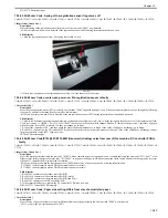
Since the error code "E674-0001" was indicated and the FAX function did not work, the main controller PCB (main) was replaced with a new one for solution.
- E674-0001 can be displayed when a communication error between FAX PCB and the main controller PCB (main) is detected in the prescribed number of
times.
Cause
Since the main controller PCB (main) was faulty, it failed to communicate with the FAX PCB, causing the error code.
Field Remedy
1. Re-fit all the connectors of the FAX board.
2. Re-fit all the connectors of the main controller PCB (main)
3. If the symptom still occurs, replace the main controller PCB (main) with a new one.
4. If the symptom still occurs, replace the FAX PCB with a new one.
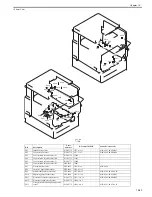
FM2-9163 Main Controller PCB Assembly
15.3.7.32 E350-0000/E732-0001/E747-051B/E747-DF00/E748-4000: Sub SJ-A board has poor contact at start-up
0016-3308
Color iR C3380G / Color iR C2880G / Color iR C3380i / Color iR C3380 / Color iR C2880i / Color iR C2880 / iR C3480 / iR C3480i / iR C3080i / iR C2550
[ Inspected by Canon Inc. ]
Description
Since the error code "E350/0000/E732-0001/E747-051B/E747-DF00/E748-4000" was displayed at start-up, the SJ-A board was re-fitted for solution.
- E732-0001 can be displayed when the DDI-S communication error occurs.
- E747-051B can be displayed when an error occurred within the Main Controller PCB (main).
- E747-DF00 can be displayed when unmounting of the Main Controller PCB (sub SJ-A) is detected.
- E748-4000 can be displayed when any ASIC of the Main Controller PCB (Sub SJ/PE/R) or ASIC of the open interface PCB is not detected.
Field Remedy
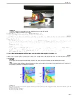
1. Re-fit the Sub SJ-A board.
2. Wipe the connector of the Sub SJ-A board with lint-free paper impregnated with alcohol, and then re-fit the board.
Note: When refitting the board, insert it as far as it will go and then tighten the screw further away from the Main Controller PCB, first.
15.3.7.33 E732-0001/E811-0001 occurs upon installation: Connector J254 hs poor contact
0016-3883
Color iR C3380G / Color iR C2880G / Color iR C3380i / Color iR C3380 / Color iR C2880i / Color iR C2880 / iR C3480 / iR C3480i / iR C3080i / iR C2550
[ Inspected by Canon Inc. ]
Description
Since J254 connector of the Controller Power Supply PCB had poor contact, the error code "E732-0001/E811-0001" was displayed.
- E732-0001 can be displayed when the DDI-S communication error occurs.
- E811-0001 can be displayed when an error in blowout of the fuse for detection of a new drum unit (process cartridge) is detected.
Field Remedy
Re-fit J254 connector of the Controller Power Supply PCB.
15.3.7.34 E732-9999 is displayed after mounting scanner
0016-3958
Color iR C3380G / Color iR C2880G / Color iR C3380i / Color iR C3380 / Color iR C2880i / Color iR C2880 / iR C3480 / iR C3480i / iR C3080i / iR C2550
[ Manual-related ]
Description
The code "E732-9999" is not an error code. This is displayed when a printer model first detects a scanner.
Field Remedy
When this code is displayed, turn the main power switch OFF/ON.
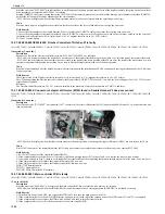
15.3.7.35 E747/E748: Procedure for mounting Sub when poor contact occurs
0016-2980
Color iR C3380G / Color iR C2880G / Color iR C3380i / Color iR C3380 / Color iR C2880i / Color iR C2880 / iR C3480 / iR C3480i / iR C3080i / iR C2550
[ Manual-related ]
Description
Depending on the mounting condition of a Sub PCB to the Controller PCB, the terminal of the Sub PCB has poor contact, causing the error code "E747" or
"E748."
Field Remedy
When re-fitting a Sub PCB to the Controller PCB, or when replacing a Sub PCB, perform the work by referring to the attached "E747/748: How to Modify
Connection of the Sub PCBs to the Controller Box."
15.3.7.36 E747-C000 is displayed at copying because paper jam occurs in front of registration area: DDI-S cable is faulty
0018-0628
Color iR C3380G / Color iR C2880G / Color iR C3380i / Color iR C3380 / Color iR C2880i / Color iR C2880 / iR C3480 / iR C3480i / iR C3080i / iR C2550
[ Inspected by Canon Inc. ]
Description
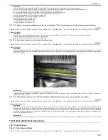
At time of copying, a paper jam occurred in front of the registration area, consequently causing the error code "E747-C000." To solve this, the DDI-S cable
was replaced with a new one.
- E747-C000 can be displayed when an error occurs in communication with the main controller PCB (sub SJ).
Cause
Since the DDI-S cable was faulty, the image data scanned by the reader was input to the printer in a state in which it was corrupted. This prevented this
machine from processing the data correctly, making the paper stop in front of the registration area.
Field Remedy
1. Re-fit the DDI-S cable.
2. If the symptom still occurs, re-fit the main controller PCB (sub SJ-A).
3. If the symptom still occurs, re-fit J502 connector of the reader controller PCB.
4. If the symptom still occurs, replace the DDI-S cable with a new one.
Summary of Contents for CiRC2550
Page 2: ......
Page 27: ...Chapter 1 Introduction ...
Page 28: ......
Page 47: ...Chapter 1 1 18 F 1 14 ON OFF ON OFF ...
Page 70: ...Chapter 1 1 41 5 Turn on the main power switch ...
Page 79: ...Chapter 2 Installation ...
Page 80: ......
Page 85: ...Chapter 2 2 3 Not available in some regions ...
Page 134: ...Chapter 3 Basic Operation ...
Page 135: ......
Page 137: ......
Page 143: ...Chapter 4 Main Controller ...
Page 144: ......
Page 152: ...Chapter 4 4 6 F 4 6 CPU HDD ROM access to the program at time of execution ...
Page 171: ...Chapter 5 Original Exposure System ...
Page 172: ......
Page 203: ...Chapter 6 Laser Exposure ...
Page 204: ......
Page 206: ......
Page 220: ...Chapter 7 Image Formation ...
Page 221: ......
Page 277: ...Chapter 8 Pickup Feeding System ...
Page 278: ......
Page 282: ......
Page 336: ...Chapter 9 Fixing System ...
Page 337: ......
Page 339: ......
Page 357: ...Chapter 10 Externals and Controls ...
Page 358: ......
Page 362: ......
Page 366: ...Chapter 10 10 4 F 10 2 F 10 3 FM1 FM2 FM5 FM8 FM11 FM4 FM3 FM6 FM7 FM9 FM10 ...
Page 375: ...Chapter 10 10 13 F 10 10 2 Remove the check mark from SNMP Status Enabled ...
Page 376: ...Chapter 10 10 14 F 10 11 ...
Page 402: ...Chapter 11 MEAP ...
Page 403: ......
Page 405: ......
Page 452: ...Chapter 12 RDS ...
Page 453: ......
Page 455: ......
Page 464: ...Chapter 13 Maintenance and Inspection ...
Page 465: ......
Page 467: ......
Page 469: ...Chapter 13 13 2 F 13 1 8 9 1 2 3 3 5 6 7 10 11 12 13 14 4 ...
Page 474: ...Chapter 14 Standards and Adjustments ...
Page 475: ......
Page 477: ......
Page 485: ......
Page 486: ...Chapter 15 Correcting Faulty Images ...
Page 487: ......
Page 495: ...Chapter 15 15 4 F 15 2 COLOR M 1 COLOR Y C K 0 ...
Page 569: ...Chapter 15 15 78 F 15 82 J102 J107 J103 J108 J101 J109 J106 J112 J115 J113 J114 J104 J105 ...
Page 570: ...Chapter 16 Self Diagnosis ...
Page 571: ......
Page 573: ......
Page 600: ...Chapter 17 Service Mode ...
Page 601: ......
Page 603: ......
Page 712: ...Chapter 18 Upgrading ...
Page 713: ......
Page 715: ......
Page 746: ...Chapter 19 Service Tools ...
Page 747: ......
Page 749: ......
Page 752: ...APPENDIX ...
Page 774: ......


