


Chapter 15
15-45
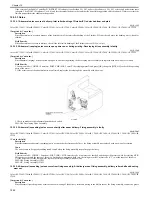
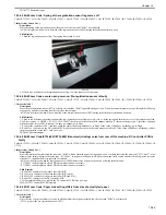
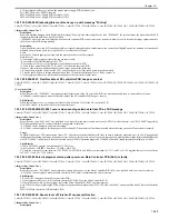
F-15-58
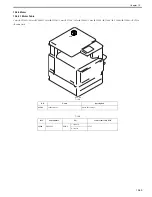
FM2-5520 Drum Drive Assembly
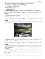
15.3.7.5 E013-0002: Connector of DC Controller PCB has poor contact
0016-4957
Color iR C3380G / Color iR C2880G / Color iR C3380i / Color iR C3380 / Color iR C2880i / Color iR C2880 / iR C3480 / iR C3480i / iR C3080i / iR C2550
[ Inspected by Canon Inc. ]
Description
Since the error code "E013-0002" occurs, all the connectors on the DC Controller PCB was disconnected and then re-connected for solution.
- E013-0002 can be displayed when inappropriate level of current (less than 50mA) is detected about 0.1 sec. after the waste toner feeding motor (M12) starts.
Field Remedy
1. Re-fit all the connectors of the DC Controller PCB.
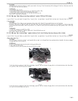
2. If Step 1 does not work on the symptom, replace the waste toner feeding motor (M12) with a new one.
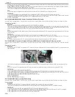
F-15-59
3. If the symptom still occurs, replace the DC Controller PCB with a new one.
FM2-9963 Waste Toner Motor Assembly
FM2-8263 DC Controller PCB Assembly
15.3.7.6 E020-0010 occurred upon installation: ATR shutter comes off
0016-0405
Color iR C3380G / Color iR C2880G / Color iR C3380i / Color iR C3380 / Color iR C2880i / Color iR C2880 / iR C3480 / iR C3480i / iR C3080i / iR C2550
[ Case in the field ]
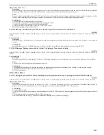
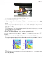
Description
After mounting the developing assemblies and toner bottles and powering on the machine upon installation, the error code "E020-0010" was indicated. To
solve this code, the ATR sensor was reseated.
Summary of Contents for CiRC2550
Page 2: ......
Page 27: ...Chapter 1 Introduction ...
Page 28: ......
Page 47: ...Chapter 1 1 18 F 1 14 ON OFF ON OFF ...
Page 70: ...Chapter 1 1 41 5 Turn on the main power switch ...
Page 79: ...Chapter 2 Installation ...
Page 80: ......
Page 85: ...Chapter 2 2 3 Not available in some regions ...
Page 134: ...Chapter 3 Basic Operation ...
Page 135: ......
Page 137: ......
Page 143: ...Chapter 4 Main Controller ...
Page 144: ......
Page 152: ...Chapter 4 4 6 F 4 6 CPU HDD ROM access to the program at time of execution ...
Page 171: ...Chapter 5 Original Exposure System ...
Page 172: ......
Page 203: ...Chapter 6 Laser Exposure ...
Page 204: ......
Page 206: ......
Page 220: ...Chapter 7 Image Formation ...
Page 221: ......
Page 277: ...Chapter 8 Pickup Feeding System ...
Page 278: ......
Page 282: ......
Page 336: ...Chapter 9 Fixing System ...
Page 337: ......
Page 339: ......
Page 357: ...Chapter 10 Externals and Controls ...
Page 358: ......
Page 362: ......
Page 366: ...Chapter 10 10 4 F 10 2 F 10 3 FM1 FM2 FM5 FM8 FM11 FM4 FM3 FM6 FM7 FM9 FM10 ...
Page 375: ...Chapter 10 10 13 F 10 10 2 Remove the check mark from SNMP Status Enabled ...
Page 376: ...Chapter 10 10 14 F 10 11 ...
Page 402: ...Chapter 11 MEAP ...
Page 403: ......
Page 405: ......
Page 452: ...Chapter 12 RDS ...
Page 453: ......
Page 455: ......
Page 464: ...Chapter 13 Maintenance and Inspection ...
Page 465: ......
Page 467: ......
Page 469: ...Chapter 13 13 2 F 13 1 8 9 1 2 3 3 5 6 7 10 11 12 13 14 4 ...
Page 474: ...Chapter 14 Standards and Adjustments ...
Page 475: ......
Page 477: ......
Page 485: ......
Page 486: ...Chapter 15 Correcting Faulty Images ...
Page 487: ......
Page 495: ...Chapter 15 15 4 F 15 2 COLOR M 1 COLOR Y C K 0 ...
Page 569: ...Chapter 15 15 78 F 15 82 J102 J107 J103 J108 J101 J109 J106 J112 J115 J113 J114 J104 J105 ...
Page 570: ...Chapter 16 Self Diagnosis ...
Page 571: ......
Page 573: ......
Page 600: ...Chapter 17 Service Mode ...
Page 601: ......
Page 603: ......
Page 712: ...Chapter 18 Upgrading ...
Page 713: ......
Page 715: ......
Page 746: ...Chapter 19 Service Tools ...
Page 747: ......
Page 749: ......
Page 752: ...APPENDIX ...
Page 774: ......


