Section 10. Processing Instructions
10-9
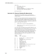
where X is the SVP
w
derived by Instruction 56. This relationship was derived by
Campbell Scientific from the equations for the SVP
w
and the SVP
i
given in
Lowe’s paper.
PAR.
DATA
NO.
TYPE
DESCRIPTION
01:
4
Input location of air temperature
o
C
[TEMP.]
02:
4
Destination input location for saturated vapour pressure
[VP or Z]
Input locations altered: 1
Instruction 57: Vapour Pressure from Wet- /Dry-Bulb
Temperatures
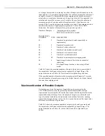
This instruction calculates vapour pressure in kilopascals from wet and dry-bulb
temperatures in
o
C. The algorithm is of the type used by the US National Weather
Service:
VP = VP
w
- A(1 + B*T
w
)(T
a
- T
w
) P
VP =
ambient vapour pressure in kilopascals
VP
w
=
saturation vapour pressure at the wet-bulb temperature in kilopascals
T
w
= wet-bulb
temperature,
o
C
T
a
=
ambient air temperature,
o
C
P
=
air pressure in kilopascals
A = 0.000660
B = 0.00115
Although the algorithm requires an air pressure entry, the daily fluctuations are
small enough that for most applications a fixed entry of the standard pressure at
the site elevation will suffice. If a pressure sensor is employed, the current
pressure can be used.
PAR.
DATA
NO.
TYPE
DESCRIPTION
01:
4
Input location of atmospheric pressure in kilopascals
[PRESSURE]
02:
4
Input location of dry-bulb temp.
[DB TEMP.]
03:
4
Input location of wet-bulb temp.
[WB TEMP.]
04:
4
Destination input location for vapour pressure
[VP or Z]
Input locations altered: 1
Instruction 58: Low Pass Filter
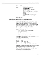
This instruction applies a numerical approximation to an analogue resistor-
capacitor (RC) low pass (LP) filter using the following algorithm:
F(X
i
) = W*X
i
+ F(X
i-1
) * (1-W)
Where, X =
input
sample
W
= user-entered weighting function,
O< W <1
F(X
i-1
) = output calculated for previous sample
If W=O, F(X
i
)=F(X
1
); if W=1, F(X
i
) =X
i


