


CR10X User Guide
7-22
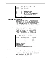
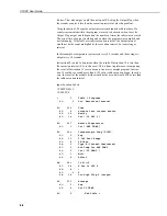
Table 7-3 Coefficient Entry Format for Paroscientific ‘T’ Series
Pressure Transducer (Instruction 65)
Coefficient
Value
Entry
U
0
5.860253
5.8603
Y
1
-3970.348
-3970.3
Y
2
-7114.265
-7114.3
* Y
3
102779.1
102.78
C
1
70.29398
70.294
C
2
6.610141
6.6101
C
3
-119.2867
-119.29
* D
1
0.0308837
30.884
D
2
0.0
0.0
T
1
26.33703
26.337
T
2
0.8516985
0.85170
T
3
21.80118
21.801
T
4
0.0
0.0
T
5
0.0
0.0
* Y
3
and D
1
coefficients are entered as Y
3
/1000 and D
1
*1000.
Only the first five digits of each 7-digit coefficient are entered in the datalogger.
The maximum error that occurs due to using 5-digit coefficients is 0.001 psi
throughout a 15 psi range at any temperature between -30 and +60
°
C. The
maximum error in temperature calculations is 0.2
°
C over the same temperature
range.
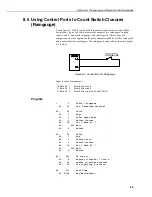
Connections
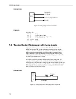
Figure 7-14 shows the components required for connecting the transducer to the
CR10X. The user-supplied components are commonly available at commercial
electronic stores.
Figure 7-14 CR10X / Paroscientific ‘T’ Series Transducer Wiring Diagram
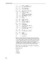
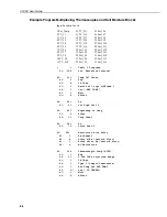
Program Example
The following example reads the coefficients from a subroutine only when the
datalogger program is compiled. The coefficients are stored in input locations 3 to
16. The temperature frequency is read on single-ended channel 1 and stored in
IN5232B