Section 9. Input/Output Instructions
9-25
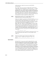
20: FP
Enhanced Parameter 17
21: FP
Enhanced Parameter 18
22: FP
Enhanced Parameter 19
23: FP
Enhanced Parameter 20
Input locations altered: 2
Instruction 100: SDM-TDR
This instruction is used to control and measure the Campbell Scientific TDR Soil
Moisture Measurement System using control ports C1, C2 and C3. See the TDR
User Guide for full details of Instruction 100.
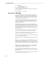
Instruction 101: SDM-INT8
The 8-channel Interval Timer (SDM-INT8) is a measurement module which sends
processed timing information to the datalogger. Each of the eight input channels
can be independently configured to detect either rising or falling edges of either a
low level AC signal or a 5V logic signal. Each channel can be programmed
independently. See the SDM-INT8 manual for detailed instructions and examples.
PARAM.
DATA
NUMBER
TYPE
DESCRIPTION
01:
2
Address of INT8
02:
4
*Input configuration; channels 8,7,6,5
03:
4
*Input configuration; channels 4,3,2,1
04:
4
**Function; channels 8,7,6,5
05:
4
**Function; channels 4,3,2,1
06:
4
***Averaging option
07:
4
Loc
08:
FP
Mult
09:
FP
Offset
Execution Time: 2.3ms + 1.65ms/value + averaging interval if used (See the
SDM-INT8 manual for possible extra processing time for higher frequency sig-
nals.)
Intermediate storage locations required:
1
* Input configurations:
0 = 5V logic level, rising edge
1 = 5V logic level, falling edge
2 = low level AC, rising edge
3 = low level AC, falling edge
** Function:
0 = none
1 = period in ms
2 = frequency in kHz
3 = time since previous channel’s edge in ms
4 = time since channel 1 in ms
5 = counts on channel 2 since channel 1, linear interpolation
6 = frequency in kHz (low resolution)
7 = counts
8 = counts on channel 2 since channel 1, no interpolation


