


Section 6. 9-Pin Serial Input/Output
6-5
communication (lowers the ME line and returns to the *0 Mode) after receiving
150 invalid characters.
6.5 Synchronous Device Communication
SDs differ from enabled peripherals in that they are not enabled solely by a
hardware line. An SD is enabled by an address synchronously clocked from the
CR10X. Up to 16 SDs may be addressed by the CR10X, requiring only three pins
of the 9-pin connector.
The Synchronous Device Communication (SDC) discussed here is for those
peripherals which connect to the 9-pin serial port. This should not be confused
with Synchronous Device for Measurement (SDM) peripherals connected to con-
trol ports 1, 2 and 3. (Although the communication protocol for SDMs is very
similar, their addressing is independent of SDC addresses and they do not have a
Ring line.)
6.5.1 SD States
The CR10X and the SDs use a combination of the Ring, Clock Handshake
(CLK/HS) and Synchronous Device Enable (SDE) lines to establish communica-
tion. The CR10X can put the SDs into one of six states.
State 1, The SD Reset State
The CR10X forces the SDs to the reset/request state by lowering the SDE and
CLK/HS lines. The SD cannot drive the CLK/HS or RXD lines in State 1.
However, it can raise the Ring line if service is needed. The SD can never pull the
Ring line low if a modem/terminal is holding it high. Data on TXD is ignored by
the SD.
State 2, The SD Addressing State
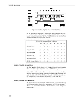
The CR10X places the SDs in the addressing state by raising CLK/HS followed
by or simultaneously raising SDE (see Figure 6-4). TXD must be low while SDE
and CLK/HS are changing to the high state.
State 2 requires all SDs to drop the Ring line and prepare for addressing. The
CR10X then synchronously clocks eight bits onto TXD using CLK/HS as a clock.
The least significant bit is transmitted first and is always logic high. Each bit
transmitted is stable on the rising edge of CLK/HS. The SDs shift in bits from
TXD on the rising edge of CLK/HS provided by the CR10X. The CR10X can
only address one device per State 2 cycle. More than one SD may respond to the
address, however. State 2 ends when the eighth bit is received by the SD.