CR10X Instruction Manual
OV-16
3.
Loaded from internal Flash memory or Storage Module on power-up.
A program is created either by entering it directly into the datalogger as described
in Section OV5, or on a PC using Edlog or the Short Cut program building
software.
Program files (.DLD extension) can be downloaded directly to the CR10X using
Campbell Scientific’s Datalogger Support Software (PC208W, PC208 or PC200).
Communication using a directly wired source as well as telephone or radio
frequency (RF) is also supported.
Programs on disk can be copied to a Storage Module using SMS (part of
PC208W) SMCOM or CSMCOM. Using the *D Mode to save or load a program
from a Storage Module is described in Section 1.
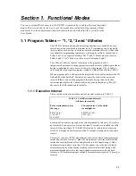
Once a program is loaded into the CR10X it will be stored in flash memory and
will be automatically loaded and executed when the datalogger is powered up.
The program on power-up function can also be achieved by using a Campbell
Scientific Storage Module. Up to eight programs can be stored in the Storage
Module. If the Storage Module is connected when the CR10X is powered up the
CR10X automatically loads program number 8, provided that a program 8 is
loaded in the Storage Module. The program from the Storage Module will replace
the program in flash memory.
OV5. Programming Examples
This section guides you through some simple programming examples. The
examples show you how to program the datalogger directly (interactively) but
remember that you can also produce datalogger programs using the Short Cut
program (part of the PC200 software package) or by using Edlog in the PC208W
and PC208 software packages.
In the following examples there is a brief explanation of each step to help you
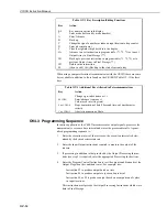
follow the logic. When the examples use an instruction, find it on the Prompt
Sheet and follow through the description of the parameters. Using the Prompt
Sheet while going through these examples will help you become familiar with its
format. Sections 9-12 have more detailed descriptions of the instructions.
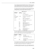
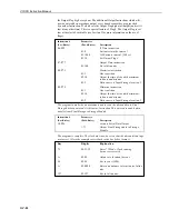
With the Wiring Panel connected to the CR10X, connect the power leads as
described in Section OV1.2. Next, connect the CR10X to either a CR10KD
Keyboard/Display or a terminal (see Section OV-3). If using a terminal, use the
7H command to get into the Remote Keyboard State. The programming steps in
the following examples use the keystrokes possible on the keyboard/display. With
a terminal, some responses will be slightly different.
If the Keyboard/Display is connected to the CR10X before the CR10X is powered
up, the ‘HELLO’ message is displayed while the CR10X checks memory. After a
few seconds the size of the usable system memory is displayed (256 for 256K
bytes of memory, 1280 for the 1Mb memory option).
When primary power is applied to the CR10X it tests the Flash memory and loads
the current program into RAM. After the program compiles successfully the
CR10X begins executing the program. If the ring line on the 9-pin connector is
raised while the CR10X is testing memory, there will be a 128 second delay
before compiling and running the program. This feature can be used to edit or
change the program before it starts running. To raise the ring line, press any key


