


CR10X Reference Manual
9-2
thermopile sensors require a jumper between LO and power ground (G) to keep
the signal inside the common mode range. The output is in millivolts.
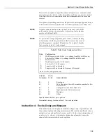
PARAM.
DATA
NUMBER
TYPE
DESCRIPTION
01:
2
Repetitions
02:
2
Range code (Table 9-1)
03:
2
Channel number for first measurement
04:
4
Input location for first measurement
05:
FP
Multiplier
06:
FP
Offset
Input locations altered:
1 per repetition
Instruction 3: Pulse Count
There are three types of pulse input which may be measured with the Pulse Count
Instruction. The Pulse Count Instruction can also be used to measure switch
closures of less than 40Hz with Control Ports 6, 7 or 8 (see Section 8).
CR23X
Pi
20k
Figure 9-1 Conditioning for Long Duration Voltage Pulses
If control ports 6, 7 or 8 are used for pulse measurement
using Instruction 3,
no counts will be measured
during the
execution of the Burst Measurement Instruction (P23).
Use separate Pulse Count Instructions when measuring both pulse channels and
control ports. All Pulse Count instructions must be kept in the same program
table. If the Pulse Count Instruction is contained within a subroutine, that
subroutine must be called from Table 2.
The use of control ports for pulse measurement causes the CR10X to use a
continuous 10 mA of power.
Input Voltage
Excessive pulse voltage inputs can damage the CR10X. Refer to Figure 9-1 if
reducing input voltage is required.
•
Pulse Channels
Maximum Input Voltage:
±
20 V
•
Control Ports
Maximum Input Voltage: 5.0 V
CAUTION
CR10X