


CR10X User Guide
4-4
In addition, an Output Array with the Array ID and five high resolution data
points (11 memory locations) is stored daily. This makes a total of 491 memory
locations per day ((20 x 24) + 11). 62280 divided by 491 = 126.8 days. Therefore,
the CR10X would have to be visited every 126 days to retrieve data, because
write-over would begin on the 127th day. Note that it is recommended that the site
is visited more frequently than this for routine maintenance, and so the data
storage capacity would not be a factor in this instance.
The output device codes used with the *8 Mode are the same as those used with
Instruction 96 (see Table 4-1), with the exception of the option to transfer data
from one Final Storage area to the other (i.e. option codes 80 and 81). Table 4-2
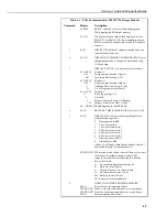
lists the keystrokes required to initiate a *8 Mode data dump.
Table 4-2 *8 Mode Entries
Display
Key
ID:DATA
Description
*8
08:00
Enter 1 or 2 for Storage Area. (This window is skipped if no
memory has been allocated to Final Storage Area 2.)
A
01:XX
Enter output device option (see Table 4-1)
A
02:XXXXX Start of dump location. Initially the SPTR or PPTR
location; a different location may be entered if desired.
A
03:XXXXX End of dump location. Initially the DSP location; a
different location may be entered if desired.
A
04:00
Ready to dump. To initiate dump, enter any number, then
press
A
. While dumping, ‘
04
’ is displayed in the ID field
and the location number in the Data field. The location
number stops incrementing when the dump is complete.
(Any key aborts transmission after completion of the current
data block.)
4.3 Use of Storage Modules (SM192 / 716 and CSM1)
The Storage Module stores data in battery-backed RAM. Backup is provided by
an internal lithium battery. The RAM is internal on the SM192/716 and on a PC
(PCMCIA) Card in the CSM1. Operating power is supplied by the CR10X over
pin 1 of the 9-pin connector. When power is applied to the Storage Module, a File
Mark is placed in the data (if a File Mark is not the last data point already in
storage).
The File Mark separates blocks of data. For example, if you retrieve data from one
CR10X, disconnect the Storage Module and connect it to a second CR10X, a File
Mark is automatically placed in the data. This mark follows the data from the first
CR10X but precedes the data from the second.
The SM192 has 192K bytes of RAM storage; the SM716 has 716K bytes. Both
can be configured as either ‘ring’ or ‘fill and stop’ memory. The capacity of the
CSM1 depends on the memory card used. The memory structure is always ‘fill
and stop’.
For information about the use of the newer SM4M and SM16M
storage modules, please see the Storage Module manual.
NOTE