


CR10X User Guide
4-6
To be certain that the SM has been connected to the CR10X during an execution
of Instruction 96, you can:
•
leave the SM connected for a time longer than an execution interval
or
•
use the SC90 9-Pin Serial Line Monitor. The SC90 contains an LED which
lights up during data transmission. Connect the SM to the CR10X with the
SC90 on the line and wait for the LED to light. When the light goes off data
transfer is complete and you can disconnect the SM from the CR10X.
4.3.3 *8 Mode Data Dump to Storage Module
In addition to the on-line data output procedures described above, output from
CR10X Final Storage to a Storage Module can be manually initiated in the *8
Mode. The procedure for setting up and transferring data is as follows:
1.
Connect the CR10KD Keyboard/Display (or computer) and the Storage
Module in parallel to the CR10 using the SC12 cable. If you are using a
computer, you will need an SC32A or SC929. See Section 5 for interfacing
details.
2.
Enter the appropriate commands as listed in Table 4-2.
4.4 *9 Mode — Commands to SM192/716 Storage
Module
A number of the following commands also apply to the
SM4M/SM16M Storage Modules – please see the Storage Module
Manual for full details.
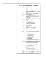
The *9 Mode is used to issue commands to an SM192/716 Storage Module (from
the CR10X) using the CR10KD or a terminal/computer. These commands are like
Functional Modes for the Storage Module and in some cases are directly
analogous to the CR10X Functional Modes. For example, command 7 enters a
mode used to review stored data, and command 8 is used to transfer data between
two Storage Modules connected to the CR10X. The operations with the Storage
Module are not directly analogous, as shown in Table 4-3 which lists the
commands (e.g. when reviewing data,
#A
advances to the start of the next Output
Array rather than to the same element in the next array with the same ID).
When
*9
is entered, the CR10X responds:
09:01
‘1’ is the default address for the Storage Module. If you have more than one
Storage Module connected, enter the address of the Storage Module you want to
communicate with. Address 1 will always work if only one Module is connected.
Press
A
and the CR10X responds:
9N:00
Where N is the address which was entered. You can now enter any of the com-
mands in Table 4-3 (key in the command number and enter it with
A
). Most
commands have at least one response; advance through these and return to the *9
command state by pressing
A
.
NOTE