77
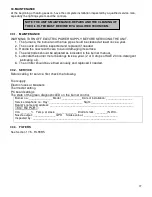
30. MAINTENANCE
At the beginning of heating season, have the complete installation inspected by a qualified service man,
especially the lighting system and the controls.
30.1. MAINTENANCE
WARNING: TURN OFF ELECTRIC POWER SUPPLY BEFORE SERVICING THE UNIT.
1. The furnace, the burner and the flue pipe should be cleaned at least once a year.
2. The nozzle should be inspected and replaced if needed.
3. Handle the nozzle with care to avoid damaging its surface.
4. The electrodes should be adjusted as indicated in the burner manual.
5. Lubricate the burner motor bearings twice a year. (2 or 3 drops of SAE 20 non-detergent
lubricating oil).
6. The oil filter should be verified annually and replaced if needed.
30.2. SERVICE
Before calling for service, first check the following
Fuel supply
Electric fuses or breakers
Thermostat setting
PC board settings
The state of the green diagnostic LED on the burner control.
Burner no.: _______________ Model: _____________ Date of installation: _________________
Service telephone no.: Day: ______________________ Night: ___________________________
Dealer’s name and address: _______________________________________________________
TEST REPORT:
CO
2
_______% Temp. at stack: ______________ Draft at stack: ________IN.W.C.
Nozzle output: _______________GPH Smoke colour: ______________________
Inspected by : _______________________________________________________
30.3. FILTERS
See Section 17.5 - FILTERS
NOTE: THE UNIT’S MAINTENANCE, REPAIRS AND THE CLEANING OF
THE OIL FILTER MUST BE DONE BY A QUALIFIED TECHNICIAN.
Summary of Contents for PF01015
Page 10: ...10 ADD ON WOOD ONLY WOOD ELECTRIC WOOD OIL ...
Page 13: ...13 INSTALLATION AND OPERATION INSTRUCTIONS CADDY ADD ON SERIAL INSTALLATION PF01015 ...
Page 16: ...16 Option 3 Option 4 ...
Page 17: ...17 EXAMPLE 1 EXAMPLE 2 ...
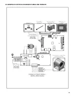
Page 63: ...63 20 GENERAL ELECTRICAL DIAGRAM STANDALONE FURNACE ...
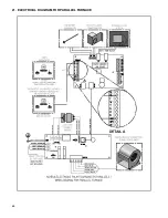
Page 64: ...64 21 ELECTRICAL DIAGRAM FOR PARALLEL FURNACE ...
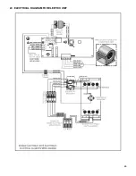
Page 65: ...65 22 ELECTRICAL DIAGRAM FOR ELECTRIC UNIT ...
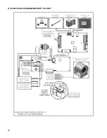
Page 78: ...78 31 ELECTRICAL DIAGRAM BECKETT OIL UNIT ...
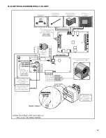
Page 79: ...79 32 ELECTRICAL DIAGRAM RIELLO OIL UNIT ...
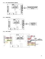
Page 81: ...81 33 4 AIR CONDITIONNING DAMPER 33 5 HUMIDIFIER 33 6 HEAT PUMP ...
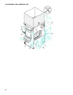
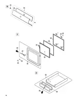
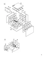
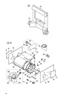
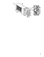
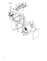
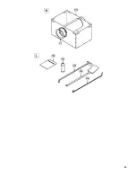
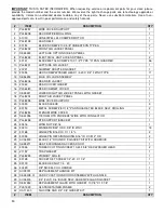
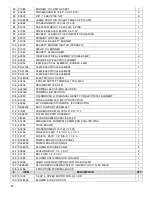
Page 82: ...82 34 EXPLODED VIEW AND PART LIST ...
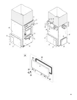
Page 83: ...83 ...
Page 84: ...84 ...
Page 85: ...85 ...
Page 86: ...86 ...
Page 87: ...87 ...
Page 88: ...88 ...
Page 89: ...89 ...

