44
15. THERMOSTAT INSTALLATION
15.1. WOOD FURNACE ONLY
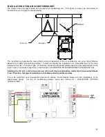
The furnace must be connected to a thermostat. You can use the one provided with the unit or use one that is already
installed in your home. The thermostat must be installed on an inside wall and located where it is not likely to be
affected by the draft coming from an air outlet. It must be installed at a minimum of 55 inches (140cm) above the floor.
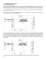
It is recommended to connect the thermostat to the furnace with a seven or eight threads wire connecting terminals
Rc, Rh C, W, Y, G, O and B.
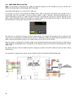
If the thermostat is using a dry contact (powered by batteries), it is not necessary to connect the C (common) terminal
to the thermostat. Refer to the electrical diagram.
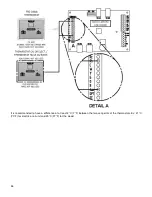
If you want to provide power to the thermostat, note that the connections may differ depending on the thermostat:
Some thermostats need Rc and C while others require Rh and C (in this case, verify the need for a jumper between Rc
and Rh in the thermostat user manual). No jumper is required with the thermostat supplied with the furnace as the Rc
and Rh are already connected together. Also, some thermostats have only the letter R. In this case, R refers to Rh.
(Connect only one of the two terminals R if there is a jumper between Rc and Rh on the thermostat). Refer to the
wiring diagram.
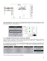
If you want to put the furnace in circulation mode from the thermostat, use the following connection diagram:
Summary of Contents for PF01015
Page 10: ...10 ADD ON WOOD ONLY WOOD ELECTRIC WOOD OIL ...
Page 13: ...13 INSTALLATION AND OPERATION INSTRUCTIONS CADDY ADD ON SERIAL INSTALLATION PF01015 ...
Page 16: ...16 Option 3 Option 4 ...
Page 17: ...17 EXAMPLE 1 EXAMPLE 2 ...
Page 63: ...63 20 GENERAL ELECTRICAL DIAGRAM STANDALONE FURNACE ...
Page 64: ...64 21 ELECTRICAL DIAGRAM FOR PARALLEL FURNACE ...
Page 65: ...65 22 ELECTRICAL DIAGRAM FOR ELECTRIC UNIT ...
Page 78: ...78 31 ELECTRICAL DIAGRAM BECKETT OIL UNIT ...
Page 79: ...79 32 ELECTRICAL DIAGRAM RIELLO OIL UNIT ...
Page 81: ...81 33 4 AIR CONDITIONNING DAMPER 33 5 HUMIDIFIER 33 6 HEAT PUMP ...
Page 82: ...82 34 EXPLODED VIEW AND PART LIST ...
Page 83: ...83 ...
Page 84: ...84 ...
Page 85: ...85 ...
Page 86: ...86 ...
Page 87: ...87 ...
Page 88: ...88 ...
Page 89: ...89 ...

