29
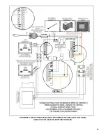
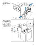
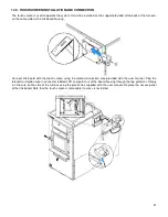
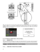
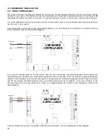
Take the telecommunication
wire and pull it through the
grommet located on the side
where the housing board is
installed.
Once the telecommunication
wire is out on the desired side,
run it along the back of the
furnace and pass it through
the grommet at the bottom of
the
link
board
housing.
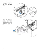
Complete the connection by
plugging
the
8
strands
telecommunication wire in the
right connector, shown by the
arrow.
Summary of Contents for PF01015
Page 10: ...10 ADD ON WOOD ONLY WOOD ELECTRIC WOOD OIL ...
Page 13: ...13 INSTALLATION AND OPERATION INSTRUCTIONS CADDY ADD ON SERIAL INSTALLATION PF01015 ...
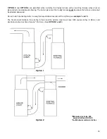
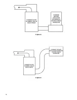
Page 16: ...16 Option 3 Option 4 ...
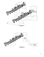
Page 17: ...17 EXAMPLE 1 EXAMPLE 2 ...
Page 63: ...63 20 GENERAL ELECTRICAL DIAGRAM STANDALONE FURNACE ...
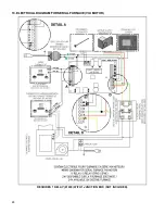
Page 64: ...64 21 ELECTRICAL DIAGRAM FOR PARALLEL FURNACE ...
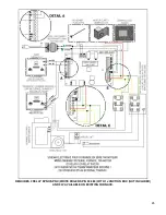
Page 65: ...65 22 ELECTRICAL DIAGRAM FOR ELECTRIC UNIT ...
Page 78: ...78 31 ELECTRICAL DIAGRAM BECKETT OIL UNIT ...
Page 79: ...79 32 ELECTRICAL DIAGRAM RIELLO OIL UNIT ...
Page 81: ...81 33 4 AIR CONDITIONNING DAMPER 33 5 HUMIDIFIER 33 6 HEAT PUMP ...
Page 82: ...82 34 EXPLODED VIEW AND PART LIST ...
Page 83: ...83 ...
Page 84: ...84 ...
Page 85: ...85 ...
Page 86: ...86 ...
Page 87: ...87 ...
Page 88: ...88 ...
Page 89: ...89 ...

