38
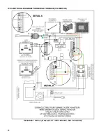
14.9. ELECTRICAL CONNECTIONS
The following instructions do not replace those of the local code.
Installation and verification of this appliance must be done by a qualified service man.
All wiring from the service panel to the heating unit must comply with the electrical code in force and all local
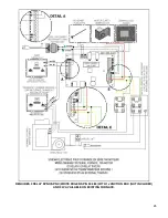
regulations. It is recommended to feed the furnace with its own electrical circuit of 15 amps at 120 volts with a breaker
(see wiring diagram).
14.10. DAMPER
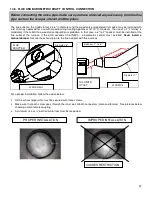
If the draft exceeds 0.06 INW.C., a barometric damper must be installed. The barometric damper must be adjusted so
that the maximum draft measured at the furnace outlet is limited to 0.06 IN.W.C. Please note that a draft higher than
0.06 IN.W.C. will reduce efficiency and could result in an uncontrollable fire.
On the other hand, the minimum draft
to be respected is 0.04 IN.W.C. in the evacuation pipe on the wood side, no matter what type of furnace is use
(WOOD, WOOD/ELECTRIC, WOOD/OIL)
14.11. COMBUSTION AIR AND FRESH AIR INTAKE ADAPTER INSTALLATION (OPTIONAL)
When the furnace and the chimney are completely cold, it may be necessary to provide fresh air by opening a door or
a window for a few minutes while lighting the fire. Take note that a house constructed or renovated in order to be
airtight may lack the volume of fresh air necessary for the proper combustion of a solid-fuel heating appliance.
In such a case, when starting up the fire, do not operate appliances that evacuate air outside the house, such as:
-
Range hood
-
Air exchanger
-
Clothes dryer
-
Bathroom fan
-
Ventilated central vacuum system
A fresh air supply may be necessary to prevent solid fuel units from rejecting products of combustion into the house.
The indications used to determine if an additional fresh air supply is necessary are not appropriate for all the situations.
When in doubt, it is recommended to install a fresh air supply.
A fresh air supply may be needed if:
-
Solid fuel units present anomalies, such as irregular draft, smoke return, bad combustion, and/or reversed
draft (whether there is combustion or not);
-
Existing solid fuel units such as a stove or fireplace release odours, heat badly, cause smoke returns, or
reversed draft (whether there is combustion or not);
-
The opening of a window, even slightly, in calm weather (windless), eliminates every problem mentioned
above;
-
The house is equipped with a tight vapour barrier and adjusted windows, and/or is equipped with an interior
air mechanical evacuation device;
-
There is excessive condensation on the windows in winter; and
-
The house is equipped with a ventilation system.
If, according to these symptoms or other similar ones, there is insufficient combustion air, it is necessary to ensure an
additional combustion air supply.
Additional combustion air can be provided with the following methods, provided that they satisfy chapter 5 of the CSA
B365 standard for Canada:
•
Direct connection: solid fuel units can be connected directly to a source of new combustion air only if they are
certified for this kind of installation, which must respect the manufacturer’s instructions. The Caddy can be installed
with an optional sealed fresh air kit that has been tested with the unit. Consult your dealer.
•
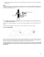
Indirect method: new combustion air can be brought into a pipe located within approximately 300 mm (12 inches)
of the unit. If the pipe is too close to the furnace, it may interfere with its operation.
•
Mechanical ventilation system: if the house is equipped with a ventilation system (air exchanger or heat recovery),
the ventilation system may provide sufficient auxiliary air to the solid fuel unit. Otherwise, the owner should be
Summary of Contents for PF01015
Page 10: ...10 ADD ON WOOD ONLY WOOD ELECTRIC WOOD OIL ...
Page 13: ...13 INSTALLATION AND OPERATION INSTRUCTIONS CADDY ADD ON SERIAL INSTALLATION PF01015 ...
Page 16: ...16 Option 3 Option 4 ...
Page 17: ...17 EXAMPLE 1 EXAMPLE 2 ...
Page 63: ...63 20 GENERAL ELECTRICAL DIAGRAM STANDALONE FURNACE ...
Page 64: ...64 21 ELECTRICAL DIAGRAM FOR PARALLEL FURNACE ...
Page 65: ...65 22 ELECTRICAL DIAGRAM FOR ELECTRIC UNIT ...
Page 78: ...78 31 ELECTRICAL DIAGRAM BECKETT OIL UNIT ...
Page 79: ...79 32 ELECTRICAL DIAGRAM RIELLO OIL UNIT ...
Page 81: ...81 33 4 AIR CONDITIONNING DAMPER 33 5 HUMIDIFIER 33 6 HEAT PUMP ...
Page 82: ...82 34 EXPLODED VIEW AND PART LIST ...
Page 83: ...83 ...
Page 84: ...84 ...
Page 85: ...85 ...
Page 86: ...86 ...
Page 87: ...87 ...
Page 88: ...88 ...
Page 89: ...89 ...

