18
WARNING
DO NOT REMOVE, RELOCATE OR BYPASS ANY OF THE SAFETY CONTROLS IN THE
ORIGINAL FURNACE INSTALLATION.
You must determine the air flow through the existing furnace before installing the Caddy wood add-on:
1. Run the furnace to which the Caddy add-on is connected until it reaches its regular heating temperature.
2. With a thermometer, measure the temperature of the fresh air entering the furnace and that of the air exiting the
furnace in the hot air plenum.
Note:
There can be a large lag in the readings of many commercially available thermometers. Give them adequate
time to stabilize when taking temperatures.
The temperature rise is obtained by subtracting the cold air return temperature from that of the air exiting in the hot air
plenum. The result (
t
) will be needed for next step.
3. Make the following verifications:
Existing oil, electric or gas furnace:
Q=
______q_____
1.08 x (T2 – T1)
Q = Flow in cubic feet/min
q = Heat flow in BTU/h
T1= Fresh air return temperature
o
F
T2= Hot air outlet temperature
o
F
11.2. PARALLEL INSTALLATION
Parallel installation with another furnace that shares the same ducts system is
not permitted in Canada
. That type of
installation is
permitted in the USA only, under certain conditions
.
For installation conditions, see Section 0 -
PARALLEL INSTALLATION.
11.3. MINIMUM CLEARANCES TO COMBUSTIBLE MATERIALS AND FLOOR PROTECTION
N.B.: This appliance must be installed in accordance with the instructions on the certification plate
applied on the unit.
Summary of Contents for PF01015
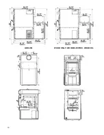
Page 10: ...10 ADD ON WOOD ONLY WOOD ELECTRIC WOOD OIL ...
Page 13: ...13 INSTALLATION AND OPERATION INSTRUCTIONS CADDY ADD ON SERIAL INSTALLATION PF01015 ...
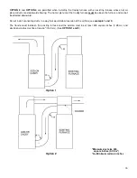
Page 16: ...16 Option 3 Option 4 ...
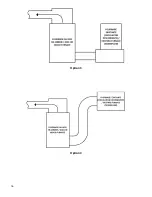
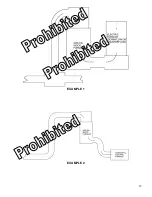
Page 17: ...17 EXAMPLE 1 EXAMPLE 2 ...
Page 63: ...63 20 GENERAL ELECTRICAL DIAGRAM STANDALONE FURNACE ...
Page 64: ...64 21 ELECTRICAL DIAGRAM FOR PARALLEL FURNACE ...
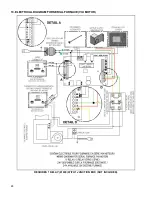
Page 65: ...65 22 ELECTRICAL DIAGRAM FOR ELECTRIC UNIT ...
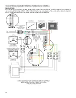
Page 78: ...78 31 ELECTRICAL DIAGRAM BECKETT OIL UNIT ...
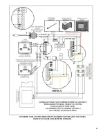
Page 79: ...79 32 ELECTRICAL DIAGRAM RIELLO OIL UNIT ...
Page 81: ...81 33 4 AIR CONDITIONNING DAMPER 33 5 HUMIDIFIER 33 6 HEAT PUMP ...
Page 82: ...82 34 EXPLODED VIEW AND PART LIST ...
Page 83: ...83 ...
Page 84: ...84 ...
Page 85: ...85 ...
Page 86: ...86 ...
Page 87: ...87 ...
Page 88: ...88 ...
Page 89: ...89 ...

