39
informed that the ventilation system may have to be rebalanced by a ventilation technician after the installation of
the solid fuel unit.
NOTE:
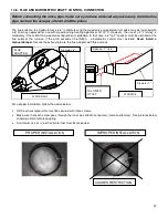
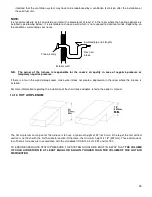
It is recommended to install an outside air inlet with a diameter of at least 4" in the room where the heating appliance is
installed (see drawing below). It is preferable to choose a wall which is not exposed to dominant winds, depending on
the conditions surrounding your house.
N.B. The owner of the furnace is responsible for the room’s air quality in case of negative pressure or
temporary negative pressure.
If there is a fan in the wood storage room, make sure it does not create a depression in the room where the furnace is
installed.
For more information regarding the installation of fresh air intake adapter, refer to the option’s manual.
14.12. HOT AIR PLENUM
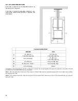
The hot air plenum coming out of the furnace is to have a minimum height of 24" (610 mm) if the top of the first vertical
section is not flush with the first horizontal section. Otherwise, the minimum height is 18" (457mm). These dimensions
for all hot air furnaces are in accordance with the standards CSA B140.4, UL 391 and UL 727.
TO ENSURE ADEQUATE STATIC PRESSURE, THE SYSTEM SHOULD BE BUILT IN A WAY THAT
THE VOLUME
OF COLD AIR RETURN IS AT LEAST EQUAL OR SLIGHTLY HIGHER THAN THE VOLUME OF THE HOT AIR
DISTRIBUTION
.
Insulated pipe (full length)
Fresh air
intake
Exterior wall
Free air entry
18”
457mm
MIN.
Summary of Contents for PF01015
Page 10: ...10 ADD ON WOOD ONLY WOOD ELECTRIC WOOD OIL ...
Page 13: ...13 INSTALLATION AND OPERATION INSTRUCTIONS CADDY ADD ON SERIAL INSTALLATION PF01015 ...
Page 16: ...16 Option 3 Option 4 ...
Page 17: ...17 EXAMPLE 1 EXAMPLE 2 ...
Page 63: ...63 20 GENERAL ELECTRICAL DIAGRAM STANDALONE FURNACE ...
Page 64: ...64 21 ELECTRICAL DIAGRAM FOR PARALLEL FURNACE ...
Page 65: ...65 22 ELECTRICAL DIAGRAM FOR ELECTRIC UNIT ...
Page 78: ...78 31 ELECTRICAL DIAGRAM BECKETT OIL UNIT ...
Page 79: ...79 32 ELECTRICAL DIAGRAM RIELLO OIL UNIT ...
Page 81: ...81 33 4 AIR CONDITIONNING DAMPER 33 5 HUMIDIFIER 33 6 HEAT PUMP ...
Page 82: ...82 34 EXPLODED VIEW AND PART LIST ...
Page 83: ...83 ...
Page 84: ...84 ...
Page 85: ...85 ...
Page 86: ...86 ...
Page 87: ...87 ...
Page 88: ...88 ...
Page 89: ...89 ...

