32
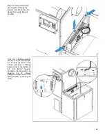
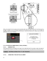
14.4. HOT AIR PLENUM TEMPERATURE PROBE INSTALLATION AND CONNECTION (RTD)
On the Caddy, a RTD has to be installed on the side of the furnace using the support provided with the unit. The RTD
is a sensor that reads the temperature inside the hot air plenum. It is critical to the good operation of the furnace. Refer
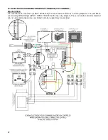
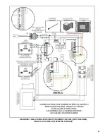
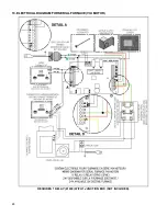
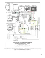
to electric diagram for connection details. It is important that the RTD and the RTD support be properly fixed onto the
hot air plenum.
WARNING: USE WIRING SUITABLE FOR 75 °C (not included).
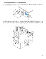
STEP 1: Remove the two screws already secured to the furnace (B) on the side where you have chosen to install the
link board. Then, secure the RTD support (A) using the two screws you previously removed.
STEP 2: Using a drill and a 9/32" bit, drill a hole in the hot air plenum so that the RTD rod can pass into it.
STEP 3 and 4: Secure the RTD in place on the hot air plenum using the two self-tapping screws provided with the
owner’s manual.
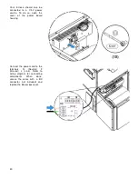
Once the RTD is installed on the support, proceed to its
connection to the link board. Pass the RTD wires in the
grommet and exit them close to the link board. For board
connections, refer to the wiring diagram.
Summary of Contents for PF01015
Page 10: ...10 ADD ON WOOD ONLY WOOD ELECTRIC WOOD OIL ...
Page 13: ...13 INSTALLATION AND OPERATION INSTRUCTIONS CADDY ADD ON SERIAL INSTALLATION PF01015 ...
Page 16: ...16 Option 3 Option 4 ...
Page 17: ...17 EXAMPLE 1 EXAMPLE 2 ...
Page 63: ...63 20 GENERAL ELECTRICAL DIAGRAM STANDALONE FURNACE ...
Page 64: ...64 21 ELECTRICAL DIAGRAM FOR PARALLEL FURNACE ...
Page 65: ...65 22 ELECTRICAL DIAGRAM FOR ELECTRIC UNIT ...
Page 78: ...78 31 ELECTRICAL DIAGRAM BECKETT OIL UNIT ...
Page 79: ...79 32 ELECTRICAL DIAGRAM RIELLO OIL UNIT ...
Page 81: ...81 33 4 AIR CONDITIONNING DAMPER 33 5 HUMIDIFIER 33 6 HEAT PUMP ...
Page 82: ...82 34 EXPLODED VIEW AND PART LIST ...
Page 83: ...83 ...
Page 84: ...84 ...
Page 85: ...85 ...
Page 86: ...86 ...
Page 87: ...87 ...
Page 88: ...88 ...
Page 89: ...89 ...

