73
27.9. ELECTRICAL WIRING
See Section 14.9 - ELECTRICAL CONNECTIONS
27.10. THERMOSTAT
See Section 15 - THERMOSTAT INSTALLATION
28. OPERATION INSTRUCTION
28.1. FAN SPEED CONTROL
See Section 16.5 - DISTRIBUTION BLOWER SPEED CONFIGURATION
28.2. COMBUSTION SAFETY CONTROL
The AFG type oil burner is equipped with an electronic control including a pre-purge function and a new,
more durable drive motor.
28.3. PRE-PURGE
When there is a call for heat, the burner’s fan will run for 15 seconds before the actual ignition takes place to
vent the combustion chamber and generate a proper draft. This will result in a smoother ignition of the oil
burner.
28.4. SAFE OPERATION
If the flame goes out while the burner is running, the control will then switch to the "RECYCLE" mode and
cut the fuel supply to the burner for 60 seconds. After this delay, the control goes back to "IGNITION"
mode. If the flame goes out 3 times in a row, the control will switch to the "LOCKOUT" mode to prevent a
continuous cycling of the ignition process, which would cause a premature soot-up of the combustion
chamber and smoke pipe. To deactivate the “LOCKOUT” mode, press and hold the reset button of the
control for 30 seconds.
A green diagnostic light on the control has four states:
- On = Flame present
- Off = No flame
- 2 seconds On, 2 seconds Off = "Recycle" mode
- 1/2 second On, 1/2 second Off = "Lockout" mode TEMPORARY SHUT-OFF
28.5. TEMPORARY DISENGAGEMENT OF THE BURNER
By pressing and holding the reset button, the burner will shut-off until the reset button is released. When the
button is released, the control will start over at the beginning of the normal cycle.
FOR ADDITIONAL INFORMATIONS ON OPERATION SEQUENCES OF THE BURNER, CONSULT THE BURNER
INSTRUCTION MANUAL.
Summary of Contents for PF01015
Page 10: ...10 ADD ON WOOD ONLY WOOD ELECTRIC WOOD OIL ...
Page 13: ...13 INSTALLATION AND OPERATION INSTRUCTIONS CADDY ADD ON SERIAL INSTALLATION PF01015 ...
Page 16: ...16 Option 3 Option 4 ...
Page 17: ...17 EXAMPLE 1 EXAMPLE 2 ...
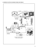
Page 63: ...63 20 GENERAL ELECTRICAL DIAGRAM STANDALONE FURNACE ...
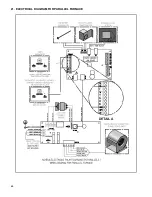
Page 64: ...64 21 ELECTRICAL DIAGRAM FOR PARALLEL FURNACE ...
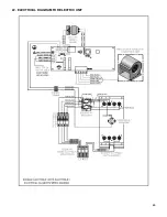
Page 65: ...65 22 ELECTRICAL DIAGRAM FOR ELECTRIC UNIT ...
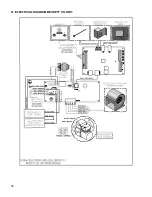
Page 78: ...78 31 ELECTRICAL DIAGRAM BECKETT OIL UNIT ...
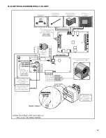
Page 79: ...79 32 ELECTRICAL DIAGRAM RIELLO OIL UNIT ...
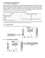
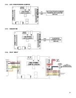
Page 81: ...81 33 4 AIR CONDITIONNING DAMPER 33 5 HUMIDIFIER 33 6 HEAT PUMP ...
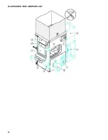
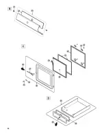
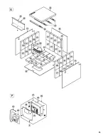
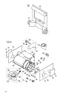
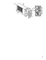
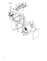
Page 82: ...82 34 EXPLODED VIEW AND PART LIST ...
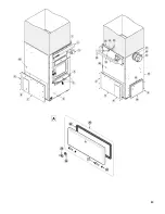
Page 83: ...83 ...
Page 84: ...84 ...
Page 85: ...85 ...
Page 86: ...86 ...
Page 87: ...87 ...
Page 88: ...88 ...
Page 89: ...89 ...

