78
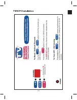
TVCB-PC Installation
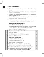
1. Determine mounting location, install screws for wall mounting
bracket
2. Determine power source location and power supply option,
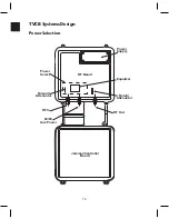
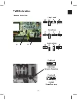
position P1 appropriately
3. Power the unit, from RF Input, Subscriber Port, or Auxiliary Port
(default from the factory)
4. Measure RF Input Levels at the tap port of the external
Directional Coupler (Channels 2 & 78)
Note:
When measuring input levels, check adjacent channels for response
flatness, use the highest value when selecting plug-in values
Minimum Input Requirements
• 9.0 dBmV @ 54 MHz (Ch. 2)
• 15.0 dBmV @ 550 MHz (Ch. 78) 5. If required for application,
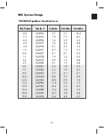
select Attenuator (AT) & Equalizer (EQ) from chart
5. Items 6 - 9 are not required for the 9111
6. Plug-in appropriate EQ and Fwd AT
7. Verify AGC Voltage
3.1 VDC optimum; 3.0 – 3.2 VDC acceptable
8. Verify unit RF Output Levels
Subscriber Port Output
• 10.0 dBmV @ 54 MHz (Ch. 2)
• 16.0 dBmV @ 600 MHz (Ch. 78)
9. Adjust EQ and AT (if necessary)
10. Select Parental Controlled Channels to be Blocked
(do not block more than 4 channels sequentially)
11. Verify blocked and unblocked channels at output port
12. Educate the customer on how to change blocked
channels on the unit, leave customer pamphlet
F
o
r
9
1
1
0
O
n
l
y
F
o
r
9
1
1
0
O
n
l
y
Summary of Contents for AMM-806
Page 86: ...79 TVCB PC Installation ...
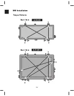
Page 93: ...86 SMI Installation Torque Patterns 1 Start Here 2 3 4 5 6 1 Start Here 2 3 4 4 PORT 8 PORT ...
Page 125: ...118 Fiber Optics Fiber Loss vs Path Length Single Mode 1550 nm ...
Page 156: ...149 Cable TV Channel Format NTSC NTSC Composite Video Waveform ...
Page 157: ...150 US Frequency Spectrum ...
Page 158: ...151 FCC Aeronautical Band Frequencies Used for Communication and Navigation ...
Page 175: ...168 Common CATV Symbols ...
Page 176: ...169 Common CATV Symbols ...
Page 177: ...170 Digital L Band Distribution Symbols ...
Page 178: ...171 Digital L Band Distribution Symbols ...
Page 183: ...176 Typical Cable Attenuation Chart in dB 100 Feet 68 F 20 C ...
Page 187: ...180 Echo Rating Graph ...
Page 188: ...181 Signal to Interference Limits Non Coherent Carriers ...
Page 190: ...183 Heterodyne Modulator Analog ...
Page 191: ...184 Heterodyne Processor Analog ...
Page 213: ...206 Multiplexers ...
Page 285: ...Rev 8 0 ...

