
44
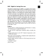
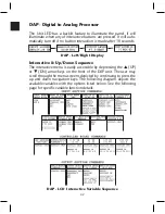
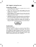
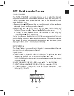
DAP - Digital to Analog Processor
INPUT CH PLAN:
The CHANNEL PLAN mode allows the user to the select the appro-
priate frequency mode. This setting alerts the user to the appropriate
center frequency plan the DAP will use during the scan process.
• The BROADCAST option must be selected for off-air 8VSB
reception, this is automatically set if the DEMOD MODE is set to
8VSB. Reception is limited to VHF & UHF center frequencies.
• The STANDARD CATV mode is capable of locking to QAM Annex
B and 8VSB signals. This channel plan is automatically set when
the QAM B mode is selected in the DEMOD MODE command
menu. Reception is limited to CATV center frequencies.
o It is only required to choose the HRC or IRC option when these
frequency off-sets are used with the CATV plan.
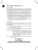
SCAN MENU:
The SCAN MENU command allows the DAP unit to auto search for
available programming. It is required to perform a scan in order to
function properly.
• YES – The YES command performs a scan of the incoming
available signals by the DAP unit
• STATUS – The STATUS command displays the channels found
during the scan process
• STOP SCAN – The STOP SCAN command permits an operator to
stop an in-process scan. It is important to note that
once a scan starts the previously found channel
data is immediately erased. If the scan is stopped,
only the completed scan channel data will be
available for selection
• EXIT – The EXIT command exits the SCAN MENU without making
any modifications
The unit will display the SCAN IN PROCESS message
during the scan process if interaction is attempted.
Summary of Contents for AMM-806
Page 86: ...79 TVCB PC Installation ...
Page 93: ...86 SMI Installation Torque Patterns 1 Start Here 2 3 4 5 6 1 Start Here 2 3 4 4 PORT 8 PORT ...
Page 125: ...118 Fiber Optics Fiber Loss vs Path Length Single Mode 1550 nm ...
Page 156: ...149 Cable TV Channel Format NTSC NTSC Composite Video Waveform ...
Page 157: ...150 US Frequency Spectrum ...
Page 158: ...151 FCC Aeronautical Band Frequencies Used for Communication and Navigation ...
Page 175: ...168 Common CATV Symbols ...
Page 176: ...169 Common CATV Symbols ...
Page 177: ...170 Digital L Band Distribution Symbols ...
Page 178: ...171 Digital L Band Distribution Symbols ...
Page 183: ...176 Typical Cable Attenuation Chart in dB 100 Feet 68 F 20 C ...
Page 187: ...180 Echo Rating Graph ...
Page 188: ...181 Signal to Interference Limits Non Coherent Carriers ...
Page 190: ...183 Heterodyne Modulator Analog ...
Page 191: ...184 Heterodyne Processor Analog ...
Page 213: ...206 Multiplexers ...
Page 285: ...Rev 8 0 ...