32
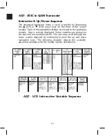
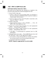
AQT - ATSC to QAM Transcoder
•
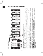
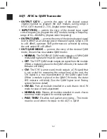
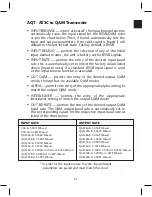
OUTPUT CATV
— permits the entry of the desired output
channel number to program the AQT module, tuning range is
NTSC CATV channel 2—135, (digital center frequency)
•
INPUT FREQ
— permits the entry of the desired input signal
center frequency to program the AQT module, tuning in frequency
range of 54—864 MHz, (digital center frequency)
•
OUTPUT LEVEL
— permits the entry of the desired output signal
level in dBmV as an average power measured signal, range is +30
to +40 dBmV, optimum SNR performance is achieved by setting
the unit output @ +40 dBmV
•
OUT QAM MODE
— permits the entry of the desired QAM
mode, the unit has six available QAM modes:
o
NORMAL
: The "NORMAL" QAM mode outputs a 6 MHz QAM
modulated signal and must be used with 8VSB input
o
OFF
: The "OFF" QAM mode outputs no signal from the module
(When a module is placed in the QAM off mode, the status LED
indicator will blink)
o
CW
: The "CW" (carrier wave) mode outputs a CW signal that
is very useful for measuring the output level of the unit, the
CW signal is a true representation of the QAM signal level
(When a module is placed in the QAM CW mode, the status
LED indicator will blink) (See the QAM Signal Level Testing
section for more detail)
o
CW ALL
: Puts all modules installed in a rack chassis into CW
mode for ease of level adjustment
o
NORMAL ALL
: Returns all modules installed in a rack chassis
to normal mode required for normal operation
o
PASS THRU
: Disables null packet processing - This mode
must be used when the input to the AQT is QAM
Summary of Contents for AMM-806
Page 86: ...79 TVCB PC Installation ...
Page 93: ...86 SMI Installation Torque Patterns 1 Start Here 2 3 4 5 6 1 Start Here 2 3 4 4 PORT 8 PORT ...
Page 125: ...118 Fiber Optics Fiber Loss vs Path Length Single Mode 1550 nm ...
Page 156: ...149 Cable TV Channel Format NTSC NTSC Composite Video Waveform ...
Page 157: ...150 US Frequency Spectrum ...
Page 158: ...151 FCC Aeronautical Band Frequencies Used for Communication and Navigation ...
Page 175: ...168 Common CATV Symbols ...
Page 176: ...169 Common CATV Symbols ...
Page 177: ...170 Digital L Band Distribution Symbols ...
Page 178: ...171 Digital L Band Distribution Symbols ...
Page 183: ...176 Typical Cable Attenuation Chart in dB 100 Feet 68 F 20 C ...
Page 187: ...180 Echo Rating Graph ...
Page 188: ...181 Signal to Interference Limits Non Coherent Carriers ...
Page 190: ...183 Heterodyne Modulator Analog ...
Page 191: ...184 Heterodyne Processor Analog ...
Page 213: ...206 Multiplexers ...
Page 285: ...Rev 8 0 ...

