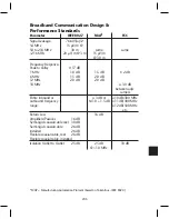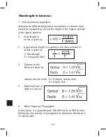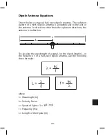
193
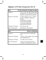
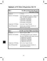
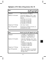
Highlights of FCC Rules & Regulations Part 76
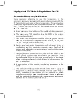
Aeronautical Frequency Notifications
Cable operators planning to use the frequencies in the
communications and navigational frequency bands must notify the
FCC prior to the activation of these frequencies. The aeronautical
operational requirements in the aeronautical bands are contained
in 47 CFR Sections 76.610-76.616. Each notification shall include
an FCC Form 159.
❏
Legal name and local address of the cable television operator;
❏
The names and FCC identifiers (e.g. CA0001) of the system
communities affected;
❏
The names and telephone numbers of local system officials
who are responsible for compliance with 76.610, 76.611, and
76.612 through 76.616 of the rules;
❏
Carrier and subcarrier frequencies and tolerance, type of
modulation and the maximum average power levels of all
carriers and subcarriers occurring at any location in the cable
distribution system;
❏
The geographical coordinates of a point near the center of the
cable system, together with the distance (in kilometers) from
the designated point to the most remote point of the cable
plant, existing or planned, which defines a circle enclosing the
entire cable plant;
❏
A description of the routine monitoring procedure to be
used;
❏
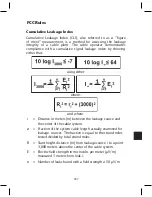
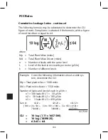
The cumulative leakage index derived under 76.611 (a)(1) or
the results of airspace measurements derived under 76.611
(a)(2), including a description of the method by which
compliance with the basic signal leakage criteria is achieved
and the method of calibrating the measurement equipment.
Use FCC Form 320 to submit the results.
Summary of Contents for AMM-806
Page 86: ...79 TVCB PC Installation ...
Page 93: ...86 SMI Installation Torque Patterns 1 Start Here 2 3 4 5 6 1 Start Here 2 3 4 4 PORT 8 PORT ...
Page 125: ...118 Fiber Optics Fiber Loss vs Path Length Single Mode 1550 nm ...
Page 156: ...149 Cable TV Channel Format NTSC NTSC Composite Video Waveform ...
Page 157: ...150 US Frequency Spectrum ...
Page 158: ...151 FCC Aeronautical Band Frequencies Used for Communication and Navigation ...
Page 175: ...168 Common CATV Symbols ...
Page 176: ...169 Common CATV Symbols ...
Page 177: ...170 Digital L Band Distribution Symbols ...
Page 178: ...171 Digital L Band Distribution Symbols ...
Page 183: ...176 Typical Cable Attenuation Chart in dB 100 Feet 68 F 20 C ...
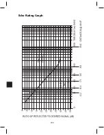
Page 187: ...180 Echo Rating Graph ...
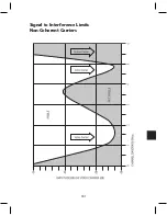
Page 188: ...181 Signal to Interference Limits Non Coherent Carriers ...
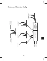
Page 190: ...183 Heterodyne Modulator Analog ...
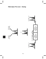
Page 191: ...184 Heterodyne Processor Analog ...
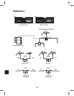
Page 213: ...206 Multiplexers ...
Page 285: ...Rev 8 0 ...

