
13
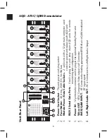
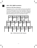
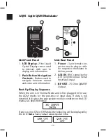
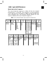
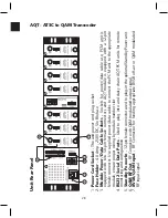
AQD - ATSC/QAM Demodulator
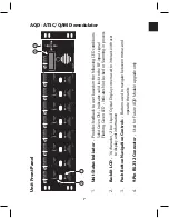
Programming a Variable
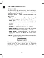
1. Use the
t
(L) or
u
(R) arrow navigation keys to scroll to the
installed module you desire to adjust.
2. Press the
▲
(UP) or
▼
(DN) arrow navigation keys to scroll to
the desired interactive variable.
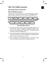
3. When a user arrives at a screen whose variable needs
to be changed, the user should depress the ENTER
button until the blinking cursor is displayed.
4. After the blinking cursor is displayed the user simply
presses the
▲
(UP) or
▼
(DN) arrow buttons to
increment or decrement to the appropriate desired value.
5. When the user reaches the desired value the user should press
the ENTER button again to apply the change to the PCM
memory. The PCM then programs the corresponding module
to the new setting.
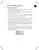
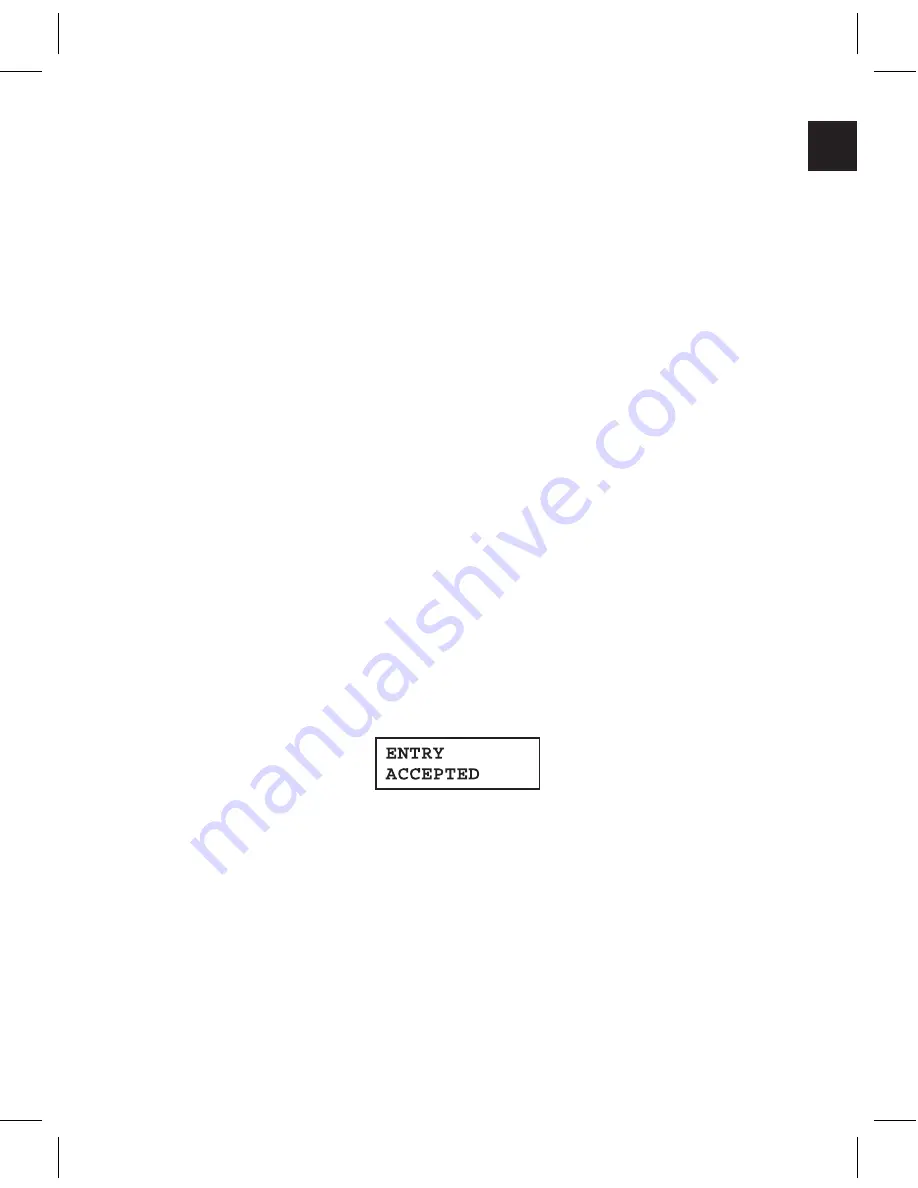
6. The LCD displays an affirmative response after information
is entered correctly for several of the variables.
The controller will display the “Entry Accepted” response as
demonstrated below.
Entry Accepted
Summary of Contents for AMM-806
Page 86: ...79 TVCB PC Installation ...
Page 93: ...86 SMI Installation Torque Patterns 1 Start Here 2 3 4 5 6 1 Start Here 2 3 4 4 PORT 8 PORT ...
Page 125: ...118 Fiber Optics Fiber Loss vs Path Length Single Mode 1550 nm ...
Page 156: ...149 Cable TV Channel Format NTSC NTSC Composite Video Waveform ...
Page 157: ...150 US Frequency Spectrum ...
Page 158: ...151 FCC Aeronautical Band Frequencies Used for Communication and Navigation ...
Page 175: ...168 Common CATV Symbols ...
Page 176: ...169 Common CATV Symbols ...
Page 177: ...170 Digital L Band Distribution Symbols ...
Page 178: ...171 Digital L Band Distribution Symbols ...
Page 183: ...176 Typical Cable Attenuation Chart in dB 100 Feet 68 F 20 C ...
Page 187: ...180 Echo Rating Graph ...
Page 188: ...181 Signal to Interference Limits Non Coherent Carriers ...
Page 190: ...183 Heterodyne Modulator Analog ...
Page 191: ...184 Heterodyne Processor Analog ...
Page 213: ...206 Multiplexers ...
Page 285: ...Rev 8 0 ...