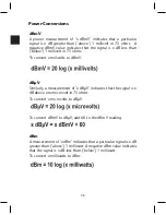
98
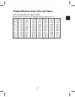
± 5% Standard Resistor Values (Ohm) Commonly available values. Values
from 10 Ohm to 22 Mega Ohm by powers of 10.
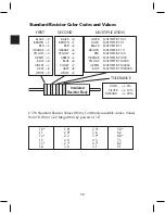
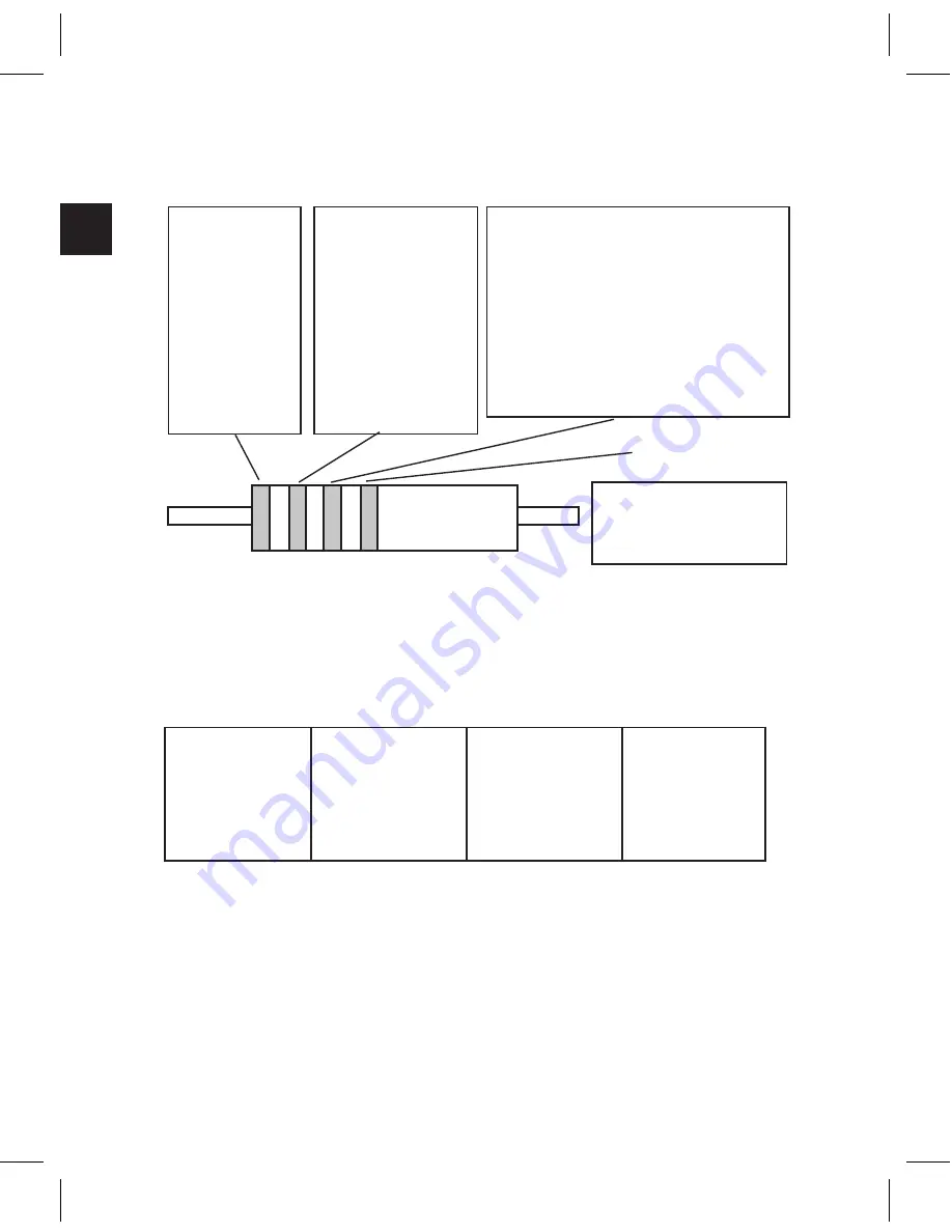
FIRST
SECOND
MULTIPLICATION
TOLERANCE
Insulated
Resistor Body
BLACK =0
BROWN =1
RED =2
ORANGE =3
YELLOW =4
GREEN =5
BLUE =6
VIOLET =7
GRAY =8
WHITE =9
BLACK =0
BROWN =1
RED =2
ORANGE =3
YELLOW =4
GREEN =5
BLUE =6
VIOLET =7
GRAY =8
WHITE =9
SILVER
MULTIPLY BY 0.01
GOLD
MULTIPLY BY 0.1
BLACK
MULTIPLY BY 1
BROWN
MULTIPLE BY 10
RED
MULTIPLY BY 100
ORANGE
MULTIPLY BY 1000
YELLOW
MULTIPLY BY 10000
GREEN
MULTIPLY BY 100000
BLUE
MULTIPLY BY 1000000
GOLD
= ± 5%
SILVER
= ± 10%
NOBAND
= ± 20%
1.0*
1.8*
3.3*
5.6*
1.1
2.0*
3.6
6.2
1.2*
2.2
3.9*
6.8*
1.3
2.4
4.3
7.5
1.5*
2.7*
4.7*
8.2
1.6
3.0
5.1
9.1
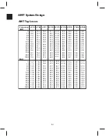
Standard Resistor Color Codes and Values
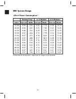
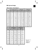
Summary of Contents for AMM-806
Page 86: ...79 TVCB PC Installation ...
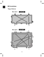
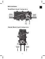
Page 93: ...86 SMI Installation Torque Patterns 1 Start Here 2 3 4 5 6 1 Start Here 2 3 4 4 PORT 8 PORT ...
Page 125: ...118 Fiber Optics Fiber Loss vs Path Length Single Mode 1550 nm ...
Page 156: ...149 Cable TV Channel Format NTSC NTSC Composite Video Waveform ...
Page 157: ...150 US Frequency Spectrum ...
Page 158: ...151 FCC Aeronautical Band Frequencies Used for Communication and Navigation ...
Page 175: ...168 Common CATV Symbols ...
Page 176: ...169 Common CATV Symbols ...
Page 177: ...170 Digital L Band Distribution Symbols ...
Page 178: ...171 Digital L Band Distribution Symbols ...
Page 183: ...176 Typical Cable Attenuation Chart in dB 100 Feet 68 F 20 C ...
Page 187: ...180 Echo Rating Graph ...
Page 188: ...181 Signal to Interference Limits Non Coherent Carriers ...
Page 190: ...183 Heterodyne Modulator Analog ...
Page 191: ...184 Heterodyne Processor Analog ...
Page 213: ...206 Multiplexers ...
Page 285: ...Rev 8 0 ...