177
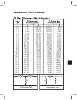
Miscellaneous Data & Constants
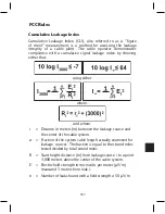
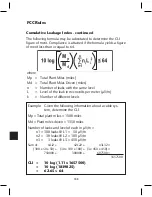
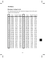
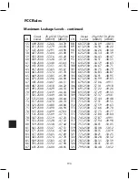
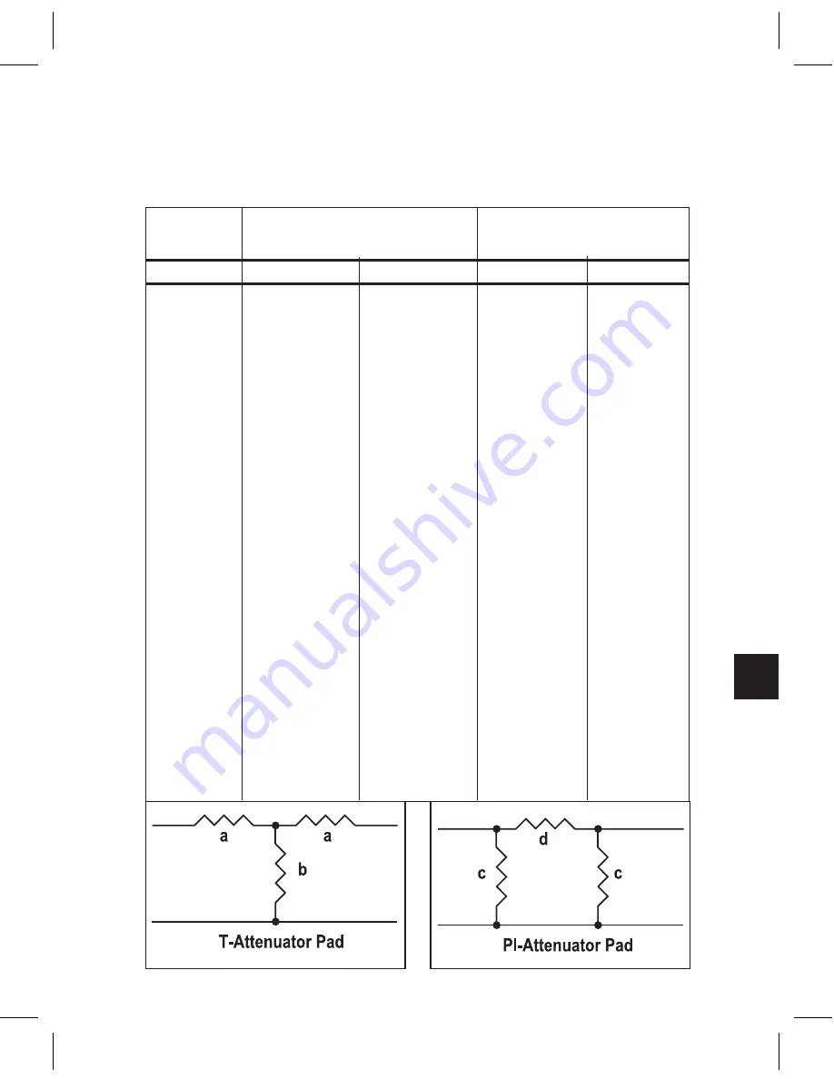
75 Ohm Attenuator Table & Equation
Loss
T-Attenuator
Pi-Attenuator
(dB)
Resistor (Ohm)
Resistor (Ohm)
a
b
c
d
0.5
2.16
1302.16
2606.49
4.32
1.0
4.31
650.00
1304.32
8.65
1.5
6.46
432.14
870.75
13.02
2.0
8.60
322.86
654.32
17.42
2.5
10.72
257.01
524.75
21.89
3.0
12.82
212.89
438.60
26.42
4.0
16.97
157.24
331.46
35.77
5.0
21.01
123.36
267.73
45.60
6.0
24.92
100.40
225.71
56.03
7.0
28.69
83.70
196.09
67.20
8.0
32.29
70.96
174.21
79.27
9.0
35.72
60.89
157.49
92.38
10.0
38.96
52.70
144.37
106.73
11.0
42.02
45.92
133.87
122.49
12.0
44.89
40.22
125.32
139.87
13.0
47.56
35.35
118.27
159.11
14.0
50.05
31.17
112.39
180.46
15.0
52.35
27.55
107.44
204.21
16.0
54.48
24.39
103.25
230.67
17.0
56.43
21.62
99.67
260.18
18.0
58.23
19.19
96.60
293.15
19.0
59.87
17.04
93.96
330.01
20.0
61.36
15.15
91.67
371.25
Summary of Contents for AMM-806
Page 86: ...79 TVCB PC Installation ...
Page 93: ...86 SMI Installation Torque Patterns 1 Start Here 2 3 4 5 6 1 Start Here 2 3 4 4 PORT 8 PORT ...
Page 125: ...118 Fiber Optics Fiber Loss vs Path Length Single Mode 1550 nm ...
Page 156: ...149 Cable TV Channel Format NTSC NTSC Composite Video Waveform ...
Page 157: ...150 US Frequency Spectrum ...
Page 158: ...151 FCC Aeronautical Band Frequencies Used for Communication and Navigation ...
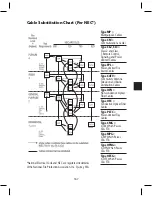
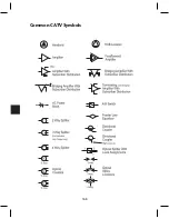
Page 175: ...168 Common CATV Symbols ...
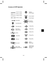
Page 176: ...169 Common CATV Symbols ...
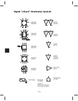
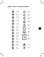
Page 177: ...170 Digital L Band Distribution Symbols ...
Page 178: ...171 Digital L Band Distribution Symbols ...
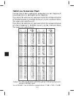
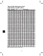
Page 183: ...176 Typical Cable Attenuation Chart in dB 100 Feet 68 F 20 C ...
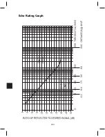
Page 187: ...180 Echo Rating Graph ...
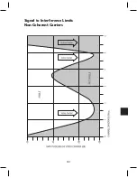
Page 188: ...181 Signal to Interference Limits Non Coherent Carriers ...
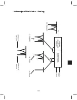
Page 190: ...183 Heterodyne Modulator Analog ...
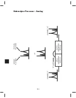
Page 191: ...184 Heterodyne Processor Analog ...
Page 213: ...206 Multiplexers ...
Page 285: ...Rev 8 0 ...