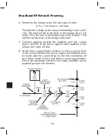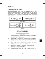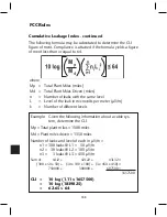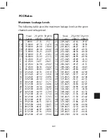
192
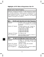
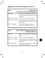
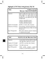
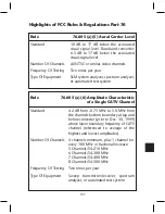
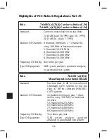
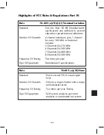
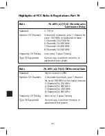
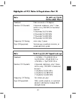
Highlights of FCC Rules & Regulations Part 76
This section is a summary of FCC specifications that CATV systems
are required to meet. This section was created so technicians and
engineers could have a ready reference at their fingertips.
All specifications in this handbook were taken from Title 47
Telecommunications, part 76.605 from the FCC. It spells out the
rule, standard, number of channels to be tested, frequency of test-
ing, and equipment needed to perform each test.
The intention of this section is to summarize FCC specifications it is
not intended to replace them. Consult the current editions of all
specifications and regulations for complete and detailed require-
ments.
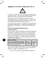
Aeronautical Operational Requirements
Frequency Offsets
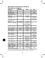
All carrier signals or signal components carried at an average power
level equal to or greater than 10-4 watts in a 25 kHz bandwidth
in any 160 microseconds period must operate at frequencies off-
set from certain frequencies which may be used by aeronautical
radio services operated by FCC licensees or by the United States
Government or its Agencies. The following table summarizes the
frequency offset requirements.
!
Frequency Offsets
Frequency Band(Standard and IRC)
Offset
Tolerance
118-137, 225-325.6 and 335.4-400 MHz
12.5 kHz
±5 kHz
108-118 and 328.6-335.4 MHz
25.0 kHz
±5 kHz
http://www.fcc.gov/Bureaus/Cable/WWW/aeronaut.html
For Harmonically Related Carrier (HRC) systems, the fundamental
frequency from which the visual carrier frequencies are derived
should be a multiple of 6.0003 MHz ±1 Hz
Summary of Contents for AMM-806
Page 86: ...79 TVCB PC Installation ...
Page 93: ...86 SMI Installation Torque Patterns 1 Start Here 2 3 4 5 6 1 Start Here 2 3 4 4 PORT 8 PORT ...
Page 125: ...118 Fiber Optics Fiber Loss vs Path Length Single Mode 1550 nm ...
Page 156: ...149 Cable TV Channel Format NTSC NTSC Composite Video Waveform ...
Page 157: ...150 US Frequency Spectrum ...
Page 158: ...151 FCC Aeronautical Band Frequencies Used for Communication and Navigation ...
Page 175: ...168 Common CATV Symbols ...
Page 176: ...169 Common CATV Symbols ...
Page 177: ...170 Digital L Band Distribution Symbols ...
Page 178: ...171 Digital L Band Distribution Symbols ...
Page 183: ...176 Typical Cable Attenuation Chart in dB 100 Feet 68 F 20 C ...
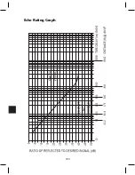
Page 187: ...180 Echo Rating Graph ...
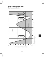
Page 188: ...181 Signal to Interference Limits Non Coherent Carriers ...
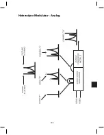
Page 190: ...183 Heterodyne Modulator Analog ...
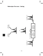
Page 191: ...184 Heterodyne Processor Analog ...
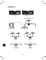
Page 213: ...206 Multiplexers ...
Page 285: ...Rev 8 0 ...

