37
DAP - Digital to Analog Processor
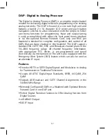
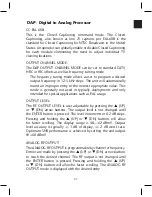
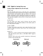
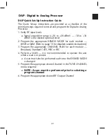
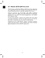
The Digital to Analog Processor (DAP) is a complete single channel
solution for delivering digital television programming over existing
analog networks. The DAP is housed in a one rack high unit and
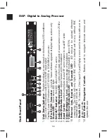
features a backlit 2 x 16 character LCD screen and push button
navigation switches to allow interaction with the simple to follow
user menu functions for programming. Input and output tuning
is easily accomplished with either the front panel menu interface
or via the optional Remote Network Card; only one RNC per
headend is needed for complete configuration and control of all
DAPs that are daisy chained in the headend. The DAP supports
standard EIA CATV, IRC, HRC and Broadcast channel plans in the
54—864 frequency range. All channel frequency information,
with appropriate FCC offsets, is pre-programmed and tuned
electronically via microprocessor. The unit is also equipped with the
Emergency Alert System (EAS) feature which can also be used as
an alternate IF input.
Features
• Decodes HDTV or SDTV Digital Signals and Modulates to Analog
for Transmission to Traditional Televisions
• Accepts All ATSC Digital Input Standards, 8VSB, 64 QAM, 256
QAM
• Outputs All Broadcast and CATV Channel Assignments in the
54-864 MHz Range
• Remotely Configure All DAPs in a Headend with Optional Remote
Network Card in one DAP unit
• Perfect Digital Transition Solution to Offer Analog Versions from
Digital Sources
• +60 dBmV Output
• EAS IF Input
Summary of Contents for AMM-806
Page 86: ...79 TVCB PC Installation ...
Page 93: ...86 SMI Installation Torque Patterns 1 Start Here 2 3 4 5 6 1 Start Here 2 3 4 4 PORT 8 PORT ...
Page 125: ...118 Fiber Optics Fiber Loss vs Path Length Single Mode 1550 nm ...
Page 156: ...149 Cable TV Channel Format NTSC NTSC Composite Video Waveform ...
Page 157: ...150 US Frequency Spectrum ...
Page 158: ...151 FCC Aeronautical Band Frequencies Used for Communication and Navigation ...
Page 175: ...168 Common CATV Symbols ...
Page 176: ...169 Common CATV Symbols ...
Page 177: ...170 Digital L Band Distribution Symbols ...
Page 178: ...171 Digital L Band Distribution Symbols ...
Page 183: ...176 Typical Cable Attenuation Chart in dB 100 Feet 68 F 20 C ...
Page 187: ...180 Echo Rating Graph ...
Page 188: ...181 Signal to Interference Limits Non Coherent Carriers ...
Page 190: ...183 Heterodyne Modulator Analog ...
Page 191: ...184 Heterodyne Processor Analog ...
Page 213: ...206 Multiplexers ...
Page 285: ...Rev 8 0 ...

