67
MegaPort Manager - Troubleshooting
How to verify that the IO is working properly
Important: All these steps are related to a MPG that has other
MPO’s that are working properly
Connect the PC to the MPO and the ping the RF port of the MPG
@ 192.168.0.1. No response, go to #1.
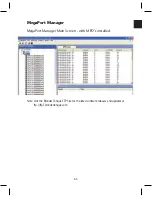
1. Ensure the MPO MAC is defined in the system using the
MegaPort Manager Software.
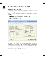
2. Open the ConfigIO and verify a green light in the link status.
If the light is red press the summary tab and observe if the IO
parameters are matching this MPG, If it matches, check for
DS RF problem.
3. Check the RF cable connection- check the cable is connected
properly.
4. Press the Monitor RF status tab and observe if the upstream
power is stable. If it is not stable check for US RF problem
5. On the PC, observe that the IO-NETWORK-DEVICE receives an
IP from the DHCP server. Open a DOS window type “ipconfig/
release” and then “ipconfig/renew”.
6. In the ConfigIO software, go to IO settings, click the “Automatic
US Power “(Uncheck the box √ ) Enter 10 at the “Static US
Power Value”, and click set.
7. Click the “Automatic US Power “ (Uncheck the box √ again )
and click set, observe if the upstream power is stable. If it is
not stable continue to number 8. Open a DOS window, type
“ipconfig/release” and then “ipconfig/renew”.
8. Connect this IO to another PC.
9. Connect this IO at another known good location that has been
tested with a PC.
Summary of Contents for AMM-806
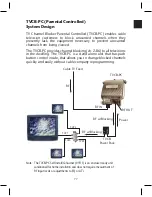
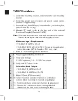
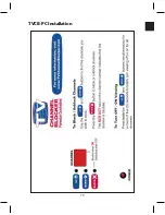
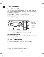
Page 86: ...79 TVCB PC Installation ...
Page 93: ...86 SMI Installation Torque Patterns 1 Start Here 2 3 4 5 6 1 Start Here 2 3 4 4 PORT 8 PORT ...
Page 125: ...118 Fiber Optics Fiber Loss vs Path Length Single Mode 1550 nm ...
Page 156: ...149 Cable TV Channel Format NTSC NTSC Composite Video Waveform ...
Page 157: ...150 US Frequency Spectrum ...
Page 158: ...151 FCC Aeronautical Band Frequencies Used for Communication and Navigation ...
Page 175: ...168 Common CATV Symbols ...
Page 176: ...169 Common CATV Symbols ...
Page 177: ...170 Digital L Band Distribution Symbols ...
Page 178: ...171 Digital L Band Distribution Symbols ...
Page 183: ...176 Typical Cable Attenuation Chart in dB 100 Feet 68 F 20 C ...
Page 187: ...180 Echo Rating Graph ...
Page 188: ...181 Signal to Interference Limits Non Coherent Carriers ...
Page 190: ...183 Heterodyne Modulator Analog ...
Page 191: ...184 Heterodyne Processor Analog ...
Page 213: ...206 Multiplexers ...
Page 285: ...Rev 8 0 ...

