

8
U
ni
t
R
ea
r
Pa
ne
l
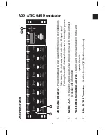
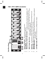
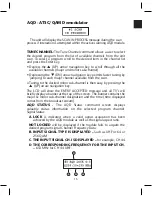
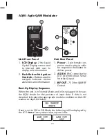
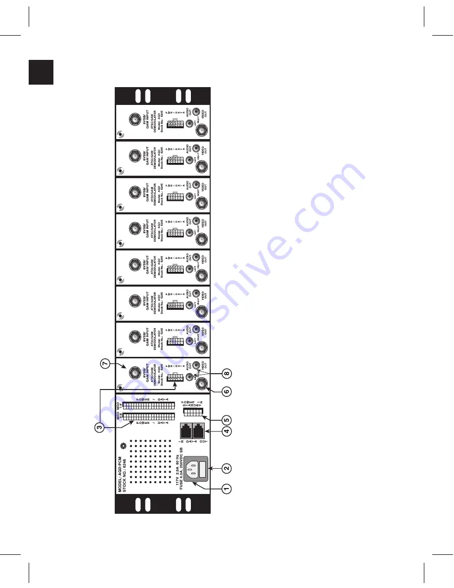
1.
P
ower
Cord
Socket
-
The
unit
power
cord
plug
socket
2.
Fuse
Holder
-
4.0
Amp.,
250V
DC,
Slo
Blo
fuse
3.
Module
P
ower/Data
Cable
Sockets
-
2
c
ab
le
s
et
s
w
ith
a
1
2-
pi
n
m
al
e
co
nn
ec
to
r
us
ed
to
deliver
power
and
data
to
each
AQD
unit
4.
RS2
32
Serial
Data
P
orts
-
U
se
d
to
p
lu
g
in
to
a
nd
d
ai
sy
c
ha
in
A
Q
D
u
ni
ts
f
or
r
em
ot
e
monitoring
and
configuration
5.
P
ower
IN
-
1
2-pin
female
connector
used
to
plug-in
the
optional
Standby
Power
unit
6.
Video
OUT
-
NTSC
C
omposite
Video
output
via
F
C
onnector
7.
8VSB/QAM
INPUT
-
R
F
C
on
ne
ct
or
fo
r f
ee
di
ng
a
pp
ro
pr
ia
te
8
VS
B
of
f-a
ir
or
Q
AM
m
od
ul
at
ed
RF
input
signal
8.
Left/Right
Audio
OUT
-
RCA
C
onnectors
for
Left/Right
Audio
Output
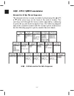
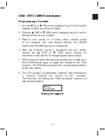
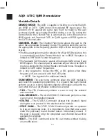
AQD - ATSC/QAM Demodulator
Summary of Contents for AMM-806
Page 86: ...79 TVCB PC Installation ...
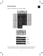
Page 93: ...86 SMI Installation Torque Patterns 1 Start Here 2 3 4 5 6 1 Start Here 2 3 4 4 PORT 8 PORT ...
Page 125: ...118 Fiber Optics Fiber Loss vs Path Length Single Mode 1550 nm ...
Page 156: ...149 Cable TV Channel Format NTSC NTSC Composite Video Waveform ...
Page 157: ...150 US Frequency Spectrum ...
Page 158: ...151 FCC Aeronautical Band Frequencies Used for Communication and Navigation ...
Page 175: ...168 Common CATV Symbols ...
Page 176: ...169 Common CATV Symbols ...
Page 177: ...170 Digital L Band Distribution Symbols ...
Page 178: ...171 Digital L Band Distribution Symbols ...
Page 183: ...176 Typical Cable Attenuation Chart in dB 100 Feet 68 F 20 C ...
Page 187: ...180 Echo Rating Graph ...
Page 188: ...181 Signal to Interference Limits Non Coherent Carriers ...
Page 190: ...183 Heterodyne Modulator Analog ...
Page 191: ...184 Heterodyne Processor Analog ...
Page 213: ...206 Multiplexers ...
Page 285: ...Rev 8 0 ...