220
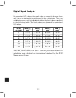
Digital Signal Analysis
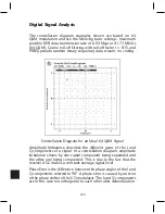
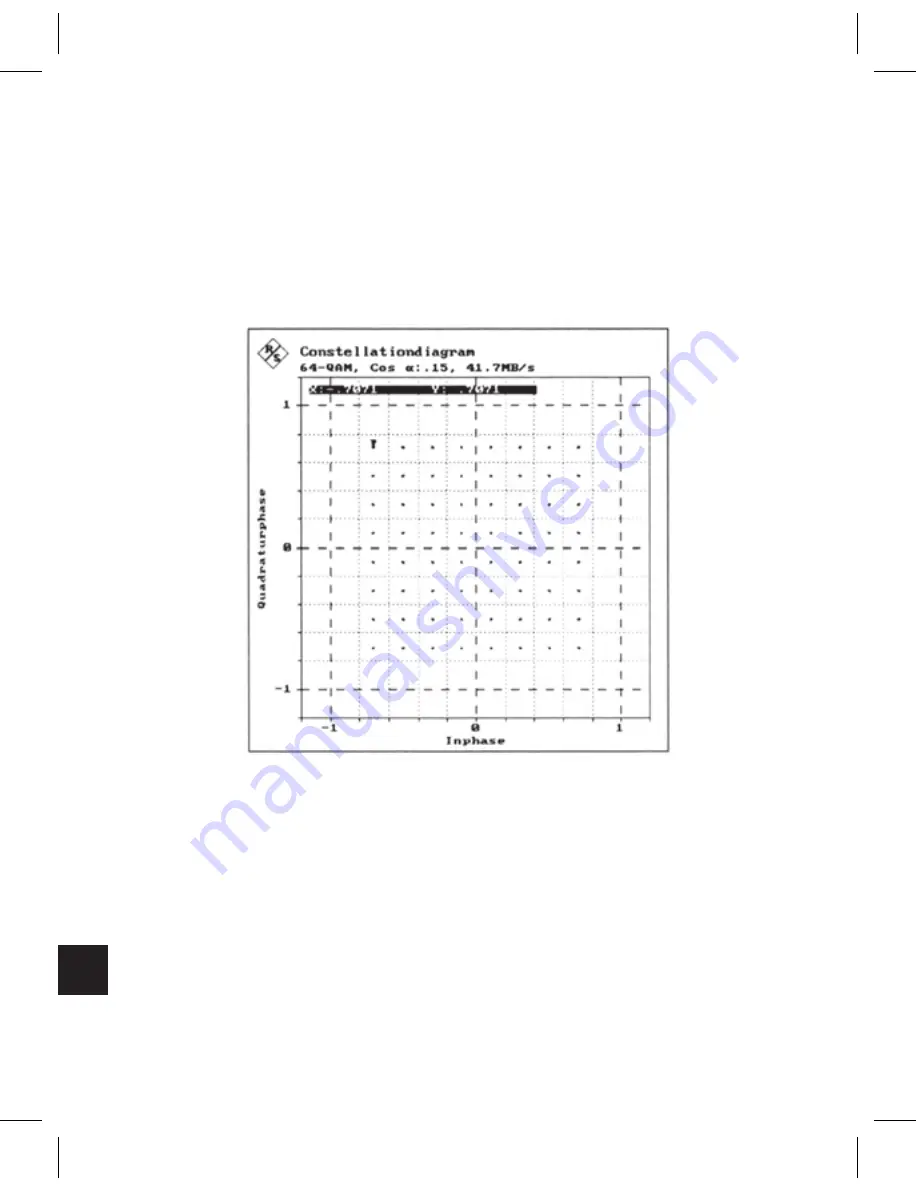
The constellation diagram examples shown are based on 64
QAM modulation and use the following basic settings: maximum
possible DVB data transmission rate of 6.92 Msps or 41.73 Mbit/s
(64 QAM); Cosine roll-off filtering with roll-off factor r = 0.15 and
PRBS (pseudo random binary sequence) data stream, no coding.
Constellation Diagram for an Ideal 64 QAM Signal
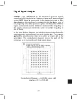
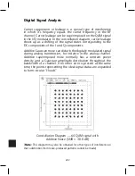
Amplitude Imbalance describes the different gains of the I and
Q components of a signal. In a constellation diagram, amplitude
imbalance shows by one signal component being expanded and
the other one being compressed. This is due to the fact that the
receiver AGC makes a constant average signal level.
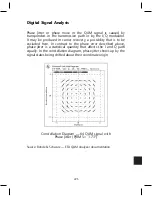
Phase Error is the difference between the phase angles of the I and
Q components referred to 90°. A phase error is caused by an error
of the phase shifter of the I/Q modulator. The I and Q components
are in this case not orthogonal to each other after demodulation.
Summary of Contents for AMM-806
Page 86: ...79 TVCB PC Installation ...
Page 93: ...86 SMI Installation Torque Patterns 1 Start Here 2 3 4 5 6 1 Start Here 2 3 4 4 PORT 8 PORT ...
Page 125: ...118 Fiber Optics Fiber Loss vs Path Length Single Mode 1550 nm ...
Page 156: ...149 Cable TV Channel Format NTSC NTSC Composite Video Waveform ...
Page 157: ...150 US Frequency Spectrum ...
Page 158: ...151 FCC Aeronautical Band Frequencies Used for Communication and Navigation ...
Page 175: ...168 Common CATV Symbols ...
Page 176: ...169 Common CATV Symbols ...
Page 177: ...170 Digital L Band Distribution Symbols ...
Page 178: ...171 Digital L Band Distribution Symbols ...
Page 183: ...176 Typical Cable Attenuation Chart in dB 100 Feet 68 F 20 C ...
Page 187: ...180 Echo Rating Graph ...
Page 188: ...181 Signal to Interference Limits Non Coherent Carriers ...
Page 190: ...183 Heterodyne Modulator Analog ...
Page 191: ...184 Heterodyne Processor Analog ...
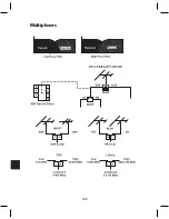
Page 213: ...206 Multiplexers ...
Page 285: ...Rev 8 0 ...