174
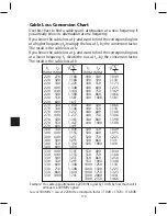
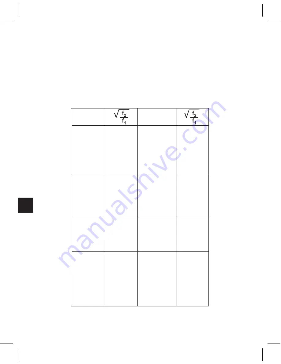
Cable Loss Conversion Chart
Use this chart to find a cable span’s attenuation at a new frequency if
you already know its attenuation at one frequency.
If you know the cable loss at f
1
and want to find the corresponding loss
at a higher frequency f
2
multiply the loss at f
1
by the conversion factor.
The result is the cable loss at f
2
.
If you know the cable loss at f
2
and want to find the corresponding loss
at a lower frequency f
1
divide the loss at f
2
by the conversion factor.
The result is the cable loss at f
1
.
Example: If a cable span attenuates a 220 MHz signal by 10 dB, by how much will it
attenuate a 300 MHz signal?
Loss at 300 MHz = Loss at 220 MHz x conversion factor = 10 dB x 1.168 = 11.68 dB
f1
f2
f1
f2
(MHz) (MHz)
(MHz) (MHz)
220 270
1.108
400 440
1.049
220 300
1.168
400 500
1.118
220 330
1.225
400 550
1.173
220 400
1.348
400 600
1.225
220 440
1.414
400 750
1.369
220 500
1.508
400 860
1.466
220 550
1.581
400 1000
1.581
220 600
1.651
270 300
1.054
440 500
1.066
270 330
1.106
440 550
1.118
270 400
1.217
440 600
1.168
270 440
1.277
440 750
1.306
270 500
1.361
440 860
1.398
270 550
1.427
440 1000
1.508
270 600
1.491
300 330
1.049
500 550
1.049
300 400
1.155
500 600
1.095
300 440
1.211
500 750
1.225
300 500
1.291
500 860
1.311
300 550
1.354
500 1000
1.414
300 600
1.414
330 400
1.101
550 600
1.044
330 440
1.155
550 750
1.168
330 500
1.231
550 860
1.250
330 550
1.291
550 1000
1.348
330 600
1.348
1000 1250
1.118
330 750
1.508
1000 1500
1.225
330 860
1.614
1000 1750
1.323
330 1000
1.741
1000 2000
1.414
1000 2150
1.466
Summary of Contents for AMM-806
Page 86: ...79 TVCB PC Installation ...
Page 93: ...86 SMI Installation Torque Patterns 1 Start Here 2 3 4 5 6 1 Start Here 2 3 4 4 PORT 8 PORT ...
Page 125: ...118 Fiber Optics Fiber Loss vs Path Length Single Mode 1550 nm ...
Page 156: ...149 Cable TV Channel Format NTSC NTSC Composite Video Waveform ...
Page 157: ...150 US Frequency Spectrum ...
Page 158: ...151 FCC Aeronautical Band Frequencies Used for Communication and Navigation ...
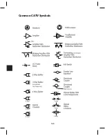
Page 175: ...168 Common CATV Symbols ...
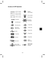
Page 176: ...169 Common CATV Symbols ...
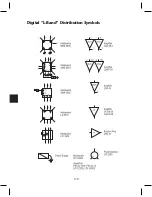
Page 177: ...170 Digital L Band Distribution Symbols ...
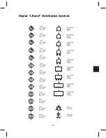
Page 178: ...171 Digital L Band Distribution Symbols ...
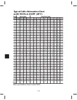
Page 183: ...176 Typical Cable Attenuation Chart in dB 100 Feet 68 F 20 C ...
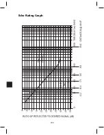
Page 187: ...180 Echo Rating Graph ...
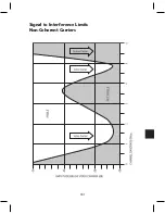
Page 188: ...181 Signal to Interference Limits Non Coherent Carriers ...
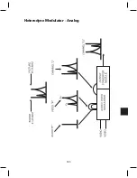
Page 190: ...183 Heterodyne Modulator Analog ...
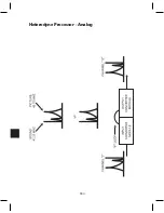
Page 191: ...184 Heterodyne Processor Analog ...
Page 213: ...206 Multiplexers ...
Page 285: ...Rev 8 0 ...

