148
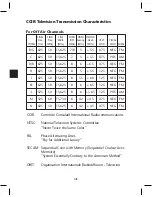
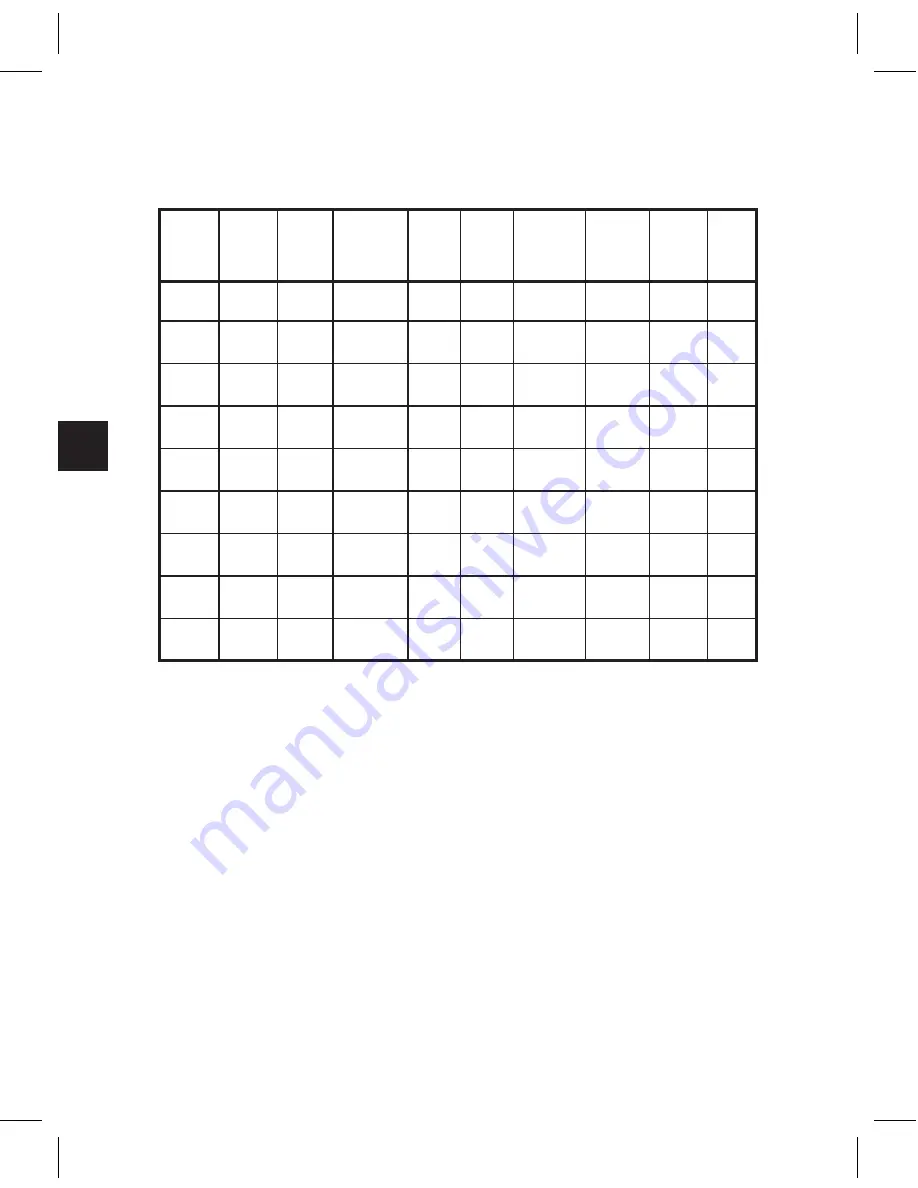
CCIR Television Transmission Characteristics
LINES
FIELD
LINE
CHAN. VIDEO VID/SND
Freq.
Freq.
Width
B/W Spacing Sideb
VEST
VISUAL
SYSTEM (Hz)
(MHz)
(MHz)
(MHz) (MHz) (MHz)
MOD
MOD AURAL
B/G 625
50 15,625 7/8
5
+ 5.5
0.75
NEG FM
C
625
50 15,625
7
5
+ 5.5
0.75
POS AM
D/K 625
50 15,625
8
6
+6.5
0.75
NEG FM
H
625
50 15,625
8
5
+ 5.5
1.25
NEG FM
I
625
50 15,625
8
5.5 + 6.0
1.25
NEG FM
K1 625
50 15,625
8
6
+ 6.5
1.25
NEG FM
L
525
50 15,625
8
6 +/- 6.5 1.25
POS AM
M
525
60 15,734
6
4.2 + 4 5
0.75
NEG FM
N
625
50 15,625
6
4.2 + 4.5
0.75
NEG FM
For Off Air Channels
CCIR: Commité Consulatif International Radiocommunications
NTSC: National Television Systems Committee
“Never Twice the Same Color”
PAL:
Phase Alternating Lines
“Pay for Additional Luxury”
SECAM: Sequential Color with Memory (Sequentiel Couleur Avec
Memoire)
“System Essentially Contrary to the American Method”
OIRT:
Organisation Internationale Radiodiffusion - Television
Summary of Contents for AMM-806
Page 86: ...79 TVCB PC Installation ...
Page 93: ...86 SMI Installation Torque Patterns 1 Start Here 2 3 4 5 6 1 Start Here 2 3 4 4 PORT 8 PORT ...
Page 125: ...118 Fiber Optics Fiber Loss vs Path Length Single Mode 1550 nm ...
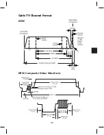
Page 156: ...149 Cable TV Channel Format NTSC NTSC Composite Video Waveform ...
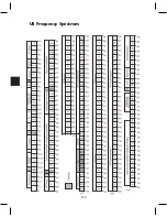
Page 157: ...150 US Frequency Spectrum ...
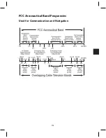
Page 158: ...151 FCC Aeronautical Band Frequencies Used for Communication and Navigation ...
Page 175: ...168 Common CATV Symbols ...
Page 176: ...169 Common CATV Symbols ...
Page 177: ...170 Digital L Band Distribution Symbols ...
Page 178: ...171 Digital L Band Distribution Symbols ...
Page 183: ...176 Typical Cable Attenuation Chart in dB 100 Feet 68 F 20 C ...
Page 187: ...180 Echo Rating Graph ...
Page 188: ...181 Signal to Interference Limits Non Coherent Carriers ...
Page 190: ...183 Heterodyne Modulator Analog ...
Page 191: ...184 Heterodyne Processor Analog ...
Page 213: ...206 Multiplexers ...
Page 285: ...Rev 8 0 ...

