background image


3


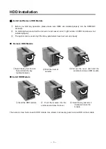
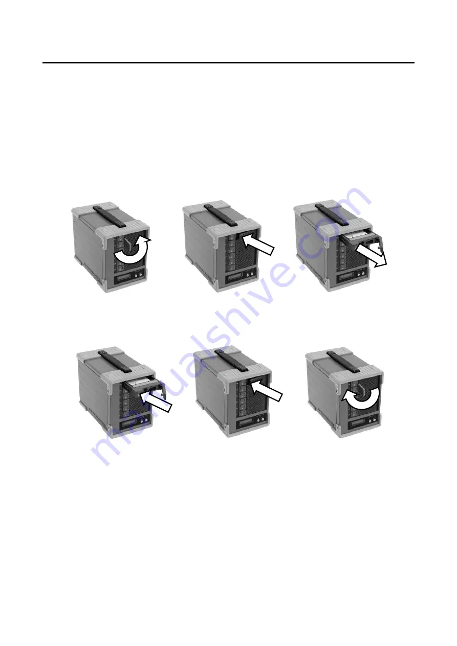
Pull  out  the  lever  and  hold  the 

canister to remove HDD module 


Insert the key and turn it 

clockwise to lock the 
module. 

 Insert the key into the lock     

hole and turn the key 
counterclockwise. 


Push the lever of 

canister 

 Insert the HDD module 

② 

Push  the  module  into  the 

enclosure and close the lever 

HDD Installation 

  Install and Remove HDD Module 

  Before  you  start  any  operation,  please  make  sure  HDDs  are  installed  properly  into  the  DVM06U3 

enclosure 

  An  alarming  beep  sound  will  be  turned  on  and  caused  error  if  right  number  of  HDD  module  was  not 

installed properly 

  The system can be used only if the Array parameters have been set up properly. 


■ 

  Remove HDD Module 


■ 

Install HDD Module 


There are 4 screw holes on each HDD module. Use screws in accessory pack to screw HDD on the module. 


Summary of Contents for DVM06U3

Page 1: ...DVM06U3 eSATA USB2 0 model 0 Best and Space Saving RAID 6 Portable 2 5 HDD 6 Desktop Model DVM06U3 USB3 1 Gen2 User Manual Revision 1 0...

Page 2: ...following provide examples of the warning drawings This symbol means that you should pay extra attention This symbol indicates something you absolutely must not do This symbol indicates necessary act...

Page 3: ...re the properties of their respective owners If you purchased a DVM06U3 storage system without preinstalled disk drives you must add disk drives into your storage before you use it Default pre install...

Page 4: ...lever HDD Installation Install and Remove HDD Module Before you start any operation please make sure HDDs are installed properly into the DVM06U3 enclosure An alarming beep sound will be turned on an...

Page 5: ...oving power cable There is a risk of electrocution Don t pull on the cable itself There is a chance of fire Never operate unless the power plug is fully inserted It may short out and generate excessiv...

Page 6: ...of the product You cannot change the order of the drives once the RAID mode has been established Please use the six drives in the order that they were installed at time of RAID creation Please be sure...

Page 7: ...places It may fall and break and may cause injury Never use with more than the rated voltage There is a risk of electrocution Don t use the cable in anything but the approved power terminal There is...

Page 8: ...D module unlock There is risk that HDD module falls out of the enclosure Never place the unit in any bags or containers containing liquids There is a risk of fire inside the unite or electrocution Kee...

Page 9: ...8...

Page 10: ...n 28 2 5 3 Quick Overview of From Panel Button Operation 29 2 6 Web based Monitor and Setup via Ethernet 30 2 6 1 Main Screen of Web GUI 30 2 6 2 Introduction of Monitor Mode 31 2 6 3 Management Mode...

Page 11: ...10 4 6 1 Transfer Rate Display 72 4 6 2 Cache Check Display 72 4 6 3 Most Delay CH Display 72 4 6 4 LCD Display for Patrol Mode Options 73 4 7 Retry Error Detection Drive SENSE DATA Display 74...

Page 12: ...ess integrated RAID system Support six hot swappable 2 5 SATA drive canisters with Lock Support RAID 6 RAID 0 RAID 3 RAID 5 RAID 10 USB3 1 10Gbits sec Theoretical value backward compatible with USB3 0...

Page 13: ...me setup Error message emailing SMTP support SNMP Trap Support Auxiliary Function Data Transfer Speed Display on LCD Each drive and host channel speed Event Display on LCD Buzzer Alarm Fault LED Indic...

Page 14: ...t bottom drive is reserved for future usage Data and Parity are distributed among 5 HDDs Since there is no assigned disk for parity each drive shares the same loading in data access Data Drive All dri...

Page 15: ...formance and security can be raised Stripe across mirrored Drive 0 1 and Drive 2 3 Capacity is equal to 2 drives capacity Data can be accessed even one of both mirrored pair drives failed The rest of...

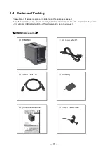
Page 16: ...s opened If you found missing items please contact your reseller And please keep the original packing carton and materials USB cable might be different depending upon the request DVM06U3 Accessories D...

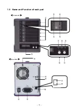
Page 17: ...16 1 5 Name and Function of each part Front side Rear Side...

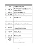
Page 18: ...see the status of module LCD Display of DVM06U3 status or parameter POWER LED Blue when system is turned on ACCESS LED Green flash when host is accessing the storage system FAIL LED Orange ON when a p...

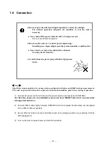
Page 19: ...teps Tips Below steps is applied to the storage unit pre configured with drives and RAID level upon procurement If the unit was procured without drives please read the quick installation guide before...

Page 20: ...dule Send back Extension Service Pack Part Number Description DVM06U3 SEDBK 1Y Extra one year send back service Total 3 years DVM06U3 SEDBK 2Y Extra two year send back service Total 4 years DVM06U3 SE...

Page 21: ...20...

Page 22: ...red Any error identified or status changed will be dynamically reflected to its respective indicators such as LED light buzzer alarm and LCD display etc Only if you wanted to change parameter setting...

Page 23: ...meters Setting mode MODE Button SELECT Button Power On Rotate among Setup items MODE Button Setup parameters SELECT Button Following selection of parameters press both MODE and SELECT button at the sa...

Page 24: ...ARRAY PARAMETERS SETTING Initial Display Disk Size Setup Hard Disk Capacity Setup RAID MODE Setup RAID Mode Setup DRIVE MODE Setup Number of Drive Setup RECOVERY MODE Setup Priority of RAID Rebuild S...

Page 25: ...than supported listing will be added in future upon firmware upgrade Please check our website for new firmware Tip Always set the size equal to claimed size of the drive Parameter Function Memo Test 1...

Page 26: ...t data access without interrupting the current host application Therefore data read write priority can be adjusted through different recovery rate setting User can choose the timing to execute recover...

Page 27: ...ule patrol all disk in 30 days cycle Default System Patrol 5 10 20 Days Cycle Calculate of the whole LUN size and schedule patrol all disk in 5 10 20 days cycle System Patrol Wait 10S 5S 3S System Pat...

Page 28: ...e faster the number is increased Push the MODE button to move to next field Again Management GUI is recommended Address Mask Setup Address Mask 255 255 255 0 This is to setup IP address mask same as I...

Page 29: ...er Default or Pre set Notes Firmware Firm ware is Ver x xxx Information only for reference Vendor ID Vender ID is BIOS Information only for reference Model No Product ID is DVM06U3 Information only fo...

Page 30: ...uring operation escape Cancel RETRY display During operation press twice Performance information Under Browsing Parameters press Use to check each drive Cache Memory Confirmation Press after Performan...

Page 31: ...rowser with IP address of the device http IP Address The Web GUI will be displayed as below for Monitor Mode The left hand side lists main menu items and the right side displays detail items or inform...

Page 32: ...re status The refreshing interval can be changed by specifying the requested time and apply Change Refresh Interval Drive status is differentiated by color Green Red Yellow White Normal One Down Two D...

Page 33: ...on main menu Basic Parameters to show basic RAID parameters Basic parameter screen shot Additional Parameters Click on main menu Additional Parameters to show additional RAID parameters Additional RA...

Page 34: ...etwork related parameters Network related parameters screen shot Logged Data Click on main menu Logged Data to show Log data of the storage Logged data screen Log data shows the historic events after...

Page 35: ...nly for firmware identification It varies from each firmware version The number 0020 0022 has special meaning for email notification error See Setup of email notification section below for explanation...

Page 36: ...ick Login for Management Mode on main menu Pop window for User Name Password to enter Management mode Default password is passwd and user name is empty To change password refer to 2 7 Setup Change Pas...

Page 37: ...After clicking To Management Menu extra menu Mail Setup and SNMP Setup will be shown on Main menu as below screen capture shown Users can configure EMAIL notification and SNMP setting so as Additiona...

Page 38: ...llowed For users who want to have more than 2 receivers you need to setup aliases on assigned email server Allowable characters are same as Sender address SMTP Server Address 255 255 255 255 Setup IP...

Page 39: ...failed after retried an error log will be recorded 0020 SMTP was not found 0021 Gateway was not found 0022 SMTP did not respond It might take up to 10 minutes for the retrial if the mail could not be...

Page 40: ...ll be sent again upon the power recycling If there are more than two events happened at the same time only the first one will be sent 2 6 6 SNMP Setup Click SNMP Setup on Main Menu and follow below st...

Page 41: ...Parameters In Management Mode you can click Additional Parameters on main menu to make the change of those parameters Additional Parameters Page Parameter settings under additional parameters can be c...

Page 42: ...41 Scroll to the parameter value you wish to change then click Change Parameters button to save the change New parameters are effective at the time right after saving...

Page 43: ...of parameters of the storage unit Power on the storage while holding both MODE and SELECT buttons about 3 seconds to Setup Mode LCD Display ARRAY PARAMETERS SETTING Launch the web browser with preset...

Page 44: ...mple LUN Size Scroll to the parameter needed to be changed and click Change Parameters button to save it Reboot the RAID system to make new parameters effective Press MODE button at first time power o...

Page 45: ...Basic Parameters Click Basic Parameters on main menu to enter Basic Parameters page Basic Parameters Page Only Read Ahead cache size is the only basic parameter Default size is 64KB Please refer to S...

Page 46: ...utton to save it Then reboot the RAID system to reflect the change Please refer to Chapter 2 for details of Mail SNMP and Log menu explanation Firmware Update Click on Update Firmware on main menu to...

Page 47: ...splay Please Wait Firm Updating Firmware is being updated Do not turn off power during firmware updating An uninterruptable power supply connection is recommended if the power source is not stable Pow...

Page 48: ...is point Instead retry again without rebooting the system If the process still failed please contact our support staff Change Password In Setup Mode click Change Password on main menu to enter Change...

Page 49: ...for each Mode with WEB GUI Menu Monitor Mode Management Mode Setup Mode Read Modify Read Modify Read Modify RAID Monitor O X O X X X Basic Parameters O X O X O O Additional Parameters O X O O O O Crit...

Page 50: ...49 2 8 Host LAN Configuration 2 8 1 IP Setup for Windows 1 Go to Start Control Panel 2 Navigate to Network and Internet Network and Sharing Center...

Page 51: ...rties First check use the following IO address Considering RAID IP ADDRESS is 192 168 50 210 set as follows IP address 192 168 50 XXX put unused address in place of XXX Subnet mask 255 255 255 0 Then...

Page 52: ...enew Enter ipconfig all Check if the IP Address has been changed correctly 2 8 2 IP Setup for Linux 1 Open a Terminal Window 2 Enter ifconfig eth0 192 168 50 X Put IP that is not used in the current n...

Page 53: ...52 2 8 3 IP Setup for MAC OS X Click System Preferences Click Network Icon...

Page 54: ...53 Choose Configure option to Manually Enter IP address and click Apply button to save it Make sure the address used here is not used by another device...

Page 55: ...54...

Page 56: ...XX XX XX XX XX root Host name root 2 Partition Creation and formatting fdisk command start fdisk Example below is when DVM06U3 is recognized as dev sdb root sheep root fdisk dev sdb Creating partition...

Page 57: ...or EXT2 FS 0 5b 95 08 09 Filesystem label OS type Linux Block size 4096 log 2 Fragment size 4096 log 2 183140352 inodes 366279984 blocks 18313999 blocks 5 00 reserved for the super user First data blo...

Page 58: ...DVM06U3 then starts with host computer Press the Start Button and right click on Computer Click on Manage Go to Device Manager Click on Disk Drives and confirm that the DVM06U3 has been registered If...

Page 59: ...n and Formatting Log into Windows 7 and click the Start then right click on Computer and click on Manage Click on Computer Management Storage Disk Management Right click Not initialize disk DISK1 then...

Page 60: ...o be initialized and move on to the formatting If DVM06U3 has capacity over 2TB in Volume then choose GPT Disk label here to able to use disk over 2TB Right click on the disk you wish to edit and clic...

Page 61: ...60 The New Volume Wizard will load up so click Next Choose the volume you want then click Next...

Page 62: ...61 8 Choose the driver letter you wish click Next 9 Choose the proper formatting settings and click Next again...

Page 63: ...ified that the settings are correct and there are no errors click Finish 11 The format will begin Close the Computer Management after the format has completed You can use the disk now please remember...

Page 64: ...OS X user guide for details 1 Confirm the connection Connect USB cable between the device and Mac computer Power on DVM06 first and then power on Mac computer If connection is fine the disk detection...

Page 65: ...64 3 Choose the disk to initialize eg 16 TB BIOS and click on Partition tab Click Partition Layout to set number of partitions you want 4 Input Partition Information as needed...

Page 66: ...65 5 Apply partition and confirm Partition 6 Choose between Backup disk or not Upon completion of partition the disk can be used to back up with Time Machine or decide later...

Page 67: ...66 7 Partition Completion...

Page 68: ...ain system power on and contact your support window There might be possibility that data will be corrupted Shutdown both computer and DVM06U3 Press and hold the MODE button then turn on DVM06U3 power...

Page 69: ...Y or blank character shown following the on LCD it might mean the drive connection is problematic In such case turn off the power and do not insert two failed drives Start with step 6 again When LCD s...

Page 70: ...ecovery there should be character R X Y or blank character shown following the on LCD it might mean the drive connection is problematic In such case turn off the power and remove the failed drive star...

Page 71: ...ve Press MODE button to stop buzzer alarm RAID x TWO DRIVE DOWN This means host access is still working under 2 failed drives status This will only be seen in RAID 6 mode Please check disk FAIL LED to...

Page 72: ...overy process has been started FAIL LED of associated drive will keep light on till the completion of recovery operation 4 5 LCD Display for FAN Failure FAN STOP NORMAL When FAN is failed system FAIL...

Page 73: ...ity LED worked normally or if HDD hang up is suspected RATE display will be exited if SCSI reset command was received Or you can press MODE and SELECT button at the same time to return to earlier stat...

Page 74: ...EAD operation will be applied to all drives and if any error sector was found they will be automatically recovered Even when the host access is continuous a read will be attempted on all drives once e...

Page 75: ...simultaneously while the DVM06U3 is in normal operation to enter Parameter display mode and then pushing them both once again RAID 6 NORMAL P A parity error occurred in the host Bus during the complet...

Page 76: ...sage Read Retry in CH Err Code x Write Retry in CH Err Code x CH 0 Drive No 0 CH 3 Drive No 3 CH 1 Drive No 1 CH 4 Drive No 4 CH 2 Drive No 2 CH 5 Drive No 5 When a drive is down an Error Sense Code w...

Reviews: