FlowStar2 LB 514
2. HPLC Monitor
19
2. HPLC Monitor
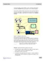
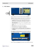
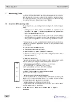
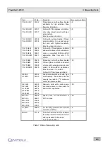
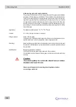
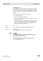
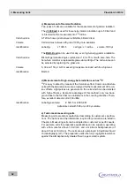
Figure 2: Measuring cell module and Radioactivity Monitor FlowStar²
FlowStar²
includes the following connection options , as illustrated in Fig-
ure 3 (rear view) and Figure 2 (front view with measuring cell module):
"Ratemeter": Analog outputs of the 2 radioactivity
channels for connec-
tion of an HPLC controller/integrator, a data system or a recorder.
"Ext. Control": External control.
Connection of start signal from injector
valve or autosampler.
"Scint. Pump": Control of scintillator pump LB 5035
with 9-pin Sub-D
socket.
Measuring cell as module on the front side
2 analog inputs
Analog In 1
and
Analog In 2
).
Connection with a PC or another data system can be established via
the
"USB"
interface
to save and analyze the measured data and to con-
trol
FlowStar²
.
All connections are established on the rear panel of the device. Mains con-
nection (
Mains
) and mains fuse (
Fuse
) are also located on the rear panel
.
Figure 3: Rear panel of FlowStar² with connection ports and terminal connections
FlowStar LB 514
2
Status
READY
Cell
Test 14C
LS-Pump
OFF
Time HH:mm:ss
ELAPSED 00:00:00
125.4
20
10
0
0
2
4
6
8
CPM
C-14
I
O
Status
READY
Cell
Test 14C
LS-Pump
OFF
Time HH:mm:ss
ELAPSED 00:00:00
125.4
20
10
0
0
2
4
6
8
CPM
C-14
IN
OUT
BERT HOLD T ECHNOLOGIES
7 5 3 2 3 Ba d Wi l d b a d
Ma d e i n Ge rma n y
ID
Nr.
VAC
Hz
VA
Trä g e Ne tzsi ch e ru n g
Sl o w Bl o w Fu se
1A
CE
USB
Pump analog
Pump RS-232
Waste / FC
W
a
st
e
V
ia
l
+
1
2
V
D
G
N
D
External Control
S
ta
rt
S
to
p
R
e
a
d
y
E
rr
o
r
W
a
it
L
u
m
i
A
u
x
O
u
t
A
u
x
i
n
+
1
2
V
D
G
N
D
Analog Output
O
u
t1
+
G
N
D
S
h
ie
ld
O
u
t2
+
G
N
D
S
h
ie
ld
Analog Input
In
1
+
In
1
-
G
N
D
In
2
+
In
2
-
G
N
D
Fuse
rating
250V/T1,0 AH
Vor Öffnen des Gerätes
Stecker ziehen.
Before opening machine
disconnect mains.
Avant d‘ouvrir l‘ appareil
retirez la fiche mâle.
Antes de abrir
el aparato sacar el enchufe.


