2. HPLC Monitor
FlowStar2 LB 514
22
2.3 Monitor Connections
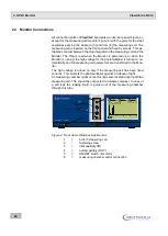
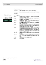
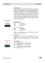
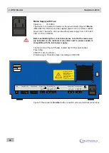
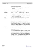
All connection ports of
FlowStar²
are located on its rear panel (Figure 5),
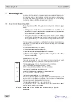
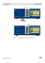
except for the measuring cell module (Figure 4) with the ports for the steel
capillaries passing the eluate to [3] and from [4] the measuring cell. The
measuring cell is inserted on the front panel and fixed by screws. This es-
tablishes contact between the chip integrated in the measuring cell and the
Monitor. The chip is read when the Monitor is powered up or when the
Monitor is running: the high voltage for the photomultiplier is turned on au-
tomatically and the measuring cell parameters are transferred to the Mon-
itor.
The high voltage is turned on only if the measuring cell has been fixed
correctly. This protects the photomultiplier against incidence of light.
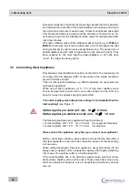
An measuring chamber outlet connector (6) is also located underneath the
measuring cell. This should be connected to a waste container. In case of
a cell leak the leaking liquid is guided out of the measuring chamber
through this tube.
Figure 4: Front view of Radioactivity Monitor
1
=
built-in measuring cell
2
=
fastening screw
3
=
inlet capillary (IN)
4
=
outlet capillary (OUT)
5
=
ON/OFF switch of monitor
6
=
measuring chamber outlet connection
FlowStar LB 514
2
Status
READY
Cell
Test 14C
LS-Pump
OFF
Time HH:mm:ss
ELAPSED 00:00:00
125.4
20
10
0
0
2
4
6
8
CPM
C-14
I
O
Status
READY
Cell
Test 14C
LS-Pump
OFF
Time HH:mm:ss
ELAPSED 00:00:00
125.4
20
10
0
0
2
4
6
8
CPM
C-14
IN
OUT
3
4
6
5
2
1
IN
OUT


