FlowStar2 LB 514
9. Parameter Entries
83
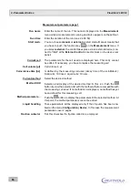
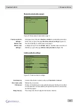
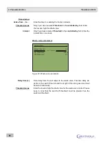
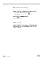
Channel 1
Active
Tick the checkbox (x) if you want to enable channel 1.
Nuclide
Select the desired nuclide. Push the
button to view the selection list
with the possible nuclides. Depending on the measuring cell used, only
the nuclides are displayed that are permitted for this measuring cell (see
nuclide table).
Background [cps]
Enter a background value, if desired. The background has to be deter-
mined by a separate measurement. The value entered here is automati-
cally subtracted from the measured value, so that net values will always
be output (on the display, the printer and the ratemeter output).
Efficiency [%]
Enter the efficiency in %. This value is used for the efficiency correction,
if it is enabled.
Spillover into chan-
nel 2 [%]
This parameter is only important for 2-channel measurements with two
different nuclides. Enter the spillover into channel 2. This parameter is
used to correct for the spillover of this nuclide into the second channel.
This correction is done after subtraction of the background.
Enter
0.0
if you do not want to carry out any spillover correction.
If you measure one nuclide with 2 channels, this parameter is not relevant
(see remarks below). In this case you also have to enter
0.0
.
Analog output
Settings for the analog output. Smoothed analog signals that are propor-
tional to the measured count rate will be output here. You have to define
the measuring range within which the count rate is to be expected.
Value at 1 V [Unit/V]
Enter the expected measuring range that corresponds to 1 V. Entering
1000 means that the measuring range is 1000 cps (with the preselected
unit cps) and corresponds to 1 V. Values above that can be presented up
to about 3V output voltage. If the count rates are within the selected
measuring range, analog signals which are proportional to the count rate
are output in the range from 0 to 1 Volt. Higher count rates are then
output linear up to 3-times this value (3 Volt).
Time constant
[FWHM]
Via the time constant you define the weighing of the smoothing of the
analog signals. The peak half-height width (FWHM) serves as measure
for the time constant. The higher the selected time constant, the more
accurate even weak peaks will be detected. On the other hand, the peak
form will be slightly flattened. Preferably one should use values of 1 and
1.5. If you enter 1, smoothing is performed over the range of one half-life
width.
You may choose: 0.5; 1; 1.5 and 2 half-height widths.
A detailed description of the smoothing feature can be found in chapter
13.1

