FlowStar2 LB 514
7. Startup of the HPLC System
55
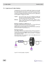
Figure 15: Configuration with solid cell
We have selected the following setup for illustration:
Two eluates are supplied via two pumps (P1 and P2) and mixed. The sample is in-
jected by an injection valve (Inj.). In the column, the sample is separated into individ-
ual components (peaks), passed through the UV detector and then to the cell in the
HPLC monitor and measured. The eluate flow is split via the 2/3-way valve (V) and
the radioactive peaks are collected in the vials of the fraction collector (FC).
- - - - - - =
connections for commands and data transfer (control lines)
=
capillary supply lines for eluate, sample and scintillator
I
0
p u rg e
s ta rt/s to p
I
0
p u rg e
s ta rt/s to p
P1
P2
UV-Detector
Mixer
Inj.
Col.
I
0
z e ro
wa v e l e n g h t
I
0
FlowStar LB 514
2
Status
READY
Cell
Test 14C
LS-Pump
OFF
125.4
20
10
0
0
2
4
6
8
CPM
C-14
Status
READY
Cell
Test 14C
LS-Pump
OFF
125.4
20
10
0
0
2
4
6
8
CPM
C-14
IN
OUT
FC
Waste
HPLC-Controller

