


FlowStar2 LB 514
1. Introduction
17
The liquid scintillator pump (LB 5037) is either controlled by the Radioac-
tivity Monitor
FlowStar
²
(through serial port) or it is controlled manually.
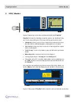
The monitor is operated via the touch screen monitor on the front panel of
the device (see Figure 2). All parameters are set and the measurements
evaluated and displayed graphically and numerically via the
FlowStar
²
software
.
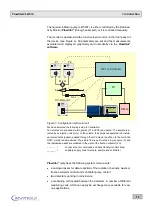
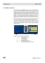
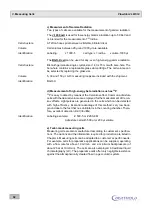
Figure 1: Configuration with solid cell
We have selected the following setup for illustration:
Two eluates are supplied via two pumps (P1 and P2) and mixed. The sample is in-
jected by an injection valve (Inj.). In the column, the sample is separated into individ-
ual components (peaks), passed through the UV detector and then to the cell in the
HPLC monitor and measured. The eluate flow is split via the 2/3-way valve (V) and
the radioactive peaks are collected in the vials of the fraction collector (FC).
- - - - - - =
connections for commands and data transfer (control lines)
_______ =
capillary supply lines for eluate, sample and scintillator
FlowStar
²
comprises the following system components:
a microprocessor for data reduction of the radiation channels, waste or
fraction collector control and scintillator pump control
two detectors working in coincidence
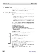
a measuring cell located between the detectors. A number of different
measuring cells, which can easily be exchanged, are available for vari-
ous applications.
I
0
p u rg e
s ta rt/s to p
I
0
p u rg e
s ta rt/s to p
P1
P2
UV-Detector
Mixer
Inj.
Col.
I
0
z e ro
wa v e l e n g h t
I
0
FlowStar LB 514
2
Status
READY
Cell
Test 14C
LS-Pump
OFF
125.4
20
10
0
0
2
4
6
8
CPM
C-14
Status
READY
Cell
Test 14C
LS-Pump
OFF
125.4
20
10
0
0
2
4
6
8
CPM
C-14
IN
OUT
FC
Waste
HPLC-Controller