7. Startup of the HPLC System
FlowStar2 LB 514
58
7.3 Installation of the Measuring Cell
7.
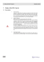
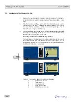
Remove the counting chamber transport protection plate on the front panel
of the HPLC Monitor which is secured by two Phillips screws (M4, 16 mm
long).
8.
Take the measuring cell you need out of the protection bag and insert it
into the module slot. Check that the O-ring seal sits properly in the groove
to ensure that the measuring chamber is protected against light. The ID
chip of the measuring cell must face up.
9.
Fix the measuring cell module with 2 of the 6 supplied socket head cap
screws (M4, 16 mm long). You find these screws, as well as the respective
screw driver, in the accessory plastic bag.
Use only 4 x 16 mm socket head cap screws!
Fix the screws only slightly first and then tighten them alternatively. Always
fix the bottom screw first, since the ID chip on the upper edge of the cell
automatically activates the high voltage for the for the light-sensitive detec-
tor (if the HPLC Monitor is turned on).
Figure 17: Front view of Radioactivity Monitor FlowStar²
1
=
built-in measuring cell
2
=
fastening screw
3
=
inlet capillary (IN)
4
=
outlet capillary (OUT)
5
=
ON/OFF switch of monitor
FlowStar LB 514
2
Status
READY
Cell
Test 14C
LS-Pump
OFF
Time HH:mm:ss
ELAPSED 00:00:00
125.4
20
10
0
0
2
4
6
8
CPM
C-14
I
O
Status
READY
Cell
Test 14C
LS-Pump
OFF
Time HH:mm:ss
ELAPSED 00:00:00
125.4
20
10
0
0
2
4
6
8
CPM
C-14
FlowStar LB 514
2
Status
READY
Cell
Test 14C
LS-Pump
OFF
Time HH:mm:ss
ELAPSED 00:00:00
125.4
20
10
0
0
2
4
6
8
CPM
C-14
I
O
Status
READY
Cell
Test 14C
LS-Pump
OFF
Time HH:mm:ss
ELAPSED 00:00:00
125.4
20
10
0
0
2
4
6
8
CPM
C-14
IN
OUT

