


Basic of Assembly
2 - 58
Electric parts and Main motor unit
Basic of Assembly
Basic of Assembly
3
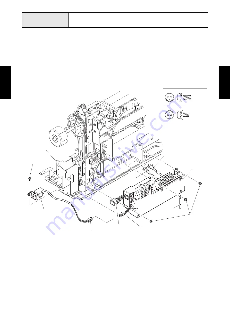
Attachment of Power unit
1. Connect the connector of inlet assy to the connector of power unit, and pass the lead wire of inlet
through the securing fixtures of power unit.
2. Pass the lead wire assy power-main and the lead wire assy motor drive through the hole of arm bed.
Attach the clip and the power unit to the arm bed with the three screws (screw, pan (S/P washer)
M4x10DB), align the boss of the inlet assy with the positioning hole of arm bed, and attach the inlet
assy with the screw (screw, pan (S/P washer) M4x8). Set the power switch assy to the SW holder.
*Key point
• Refer to
.
Refer to 3 - 122 Assembly of Power unit.
Screw, Pan (S/P washer) M4X10DB
Screw, Pan (S/P washer) M4X8
Inlet assy
Connector of inlet assy
Screw, pan
(S/P washer) M4x8
Screw, pan
(S/P washer)
M4x10DB
Power unit
Connector of
power unit
Lead wire assy power-main
Lead wire assy
motor drive
SW holder
Power switch assy
Clip
Summary of Contents for BLDY
Page 2: ......