


Application of
Assembly
3 - 208
Embroidery unit
Application o
f
Assembly
Application of
Assembly
17
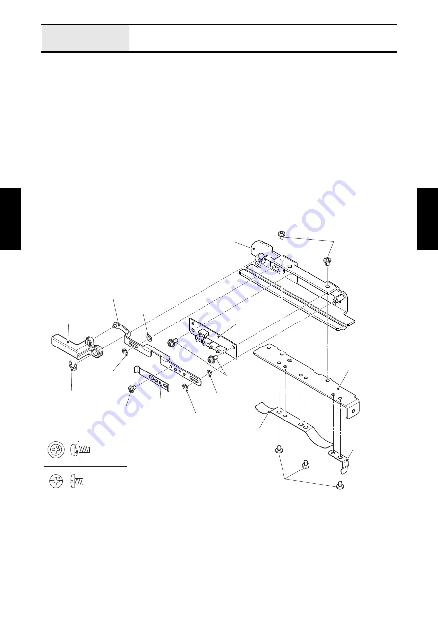
Assembly of E hoop stay plate assy
1. Align the positioning hole of frame sensor PCB assy with the boss of E hoop stay plate assy, and attach
the frame sensor PCB assy to the E hoop stay plate assy with the two screws (screw, pan (S/P washer)
M3x7).
2. Set the two polyester sliders and lock SW plate sub assy to the two shafts of E hoop stay plate assy,
and attach the two retaining rings E2.5.
3. Align the positioning groove of E hoop lock lever with the pin of lock SW plate sub assy, set the E hoop
lock lever to the E hoop stay plate assy, and attach the retaining ring E4.
4. Attach the hoop lock SW push plate to the lock SW plate sub assy with the screw (screw, bind M3x4).
*Key point
• Check if the switch of frame sensor PCB assy works by moving E hoop lock lever.
5. Align the positioning hole of E hoop pressure spring C with the boss of E hoop pressure plate, and
attach the E hoop pressure spring C to the E hoop pressure plate with the screw (screw, bind M3x4).
Align the two positioning holes of E hoop pressure spring A with the two bosses of E hoop pressure
plate, and attach the E hoop pressure spring A to the E hoop pressure plate with the two screws
(screw, bind M3x4). Attach the E hoop pressure plate to the E hoop stay plate assy with the two screws
(screw, bind M3x4).
Screw, Bind M3X4
Screw, Pan (S/P washer) M3X7
Screw, bind M3x4
E hoop stay plate assy
Frame sensor
PCB assy
Polyester slider
Lock SW plate sub assy
E hoop lock lever
Retaining ring E4
Screw, bind M3x4
Screw, pan
(S/P washer) M3x7
E hoop pressure plate
E hoop pressure
spring C
E hoop pressure spring A
Screw, bind M3x4
Retaining ring E2.5
Polyester slider
Retaining ring E2.5
Hoop lock SW
push plate
Summary of Contents for BLDY
Page 2: ......