


Application of
Assembly
3 - 161
Needle-presser module
Application o
f
Assembly
Application of
Assembly
10
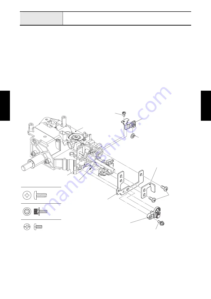
Attachment of Needle holder block base, Presser bar support plate,
Needle holder block assy and W presser adjust plate
1. Align the two positioning holes of needle holder block base with the two bosses of upper unit holder
assy, and attach the needle holder block base to the upper unit holder assy with the screw (taptite, bind
B M4x10). Align the positioning hole of presser bar support plate with the boss of upper unit holder
assy, and attach the presser bar support plate to the upper unit holder assy with the screw (taptite, bind
B M4x10).
2. Insert the shaft of needle holder block assy into the positioning hole of needle holder block base, and
set the needle holder block assy to the boss of the needle bar supporter assy, then set the needle
holder block assy to the needle holder block base, and tighten the screw (screw 3x10) temporarily.
*Key point
• Fully tighten the screw after performing
"Adjustment of Needle clearance left/right"
3. Set the needle bar felt to the W presser adjust plate. Align the boss of W presser adjust plate with the
positioning hole of needle bar supporter assy, set the W presser adjust plate to the needle bar
supporter assy, and tighten the screw (screw, bind M3x6) temporarily.
*Key point
• Fully tighten the screw after the needle bar attachment.
Screw, Bind M3X6
Taptite, Bind B M4X10
Screw 3X10
Upper unit holder assy
Boss
Needle holder block base
Presser bar support plate
Taptite, bind B
M4x10
Screw, bind M3x6
Needle holder block assy
Screw 3x10
W presser adjust plate
Needle bar felt
Needle bar supporter assy
Summary of Contents for BLDY
Page 2: ......