


Application of
Assembly
3 - 171
Needle-presser module
Application o
f
Assembly
Application of
Assembly
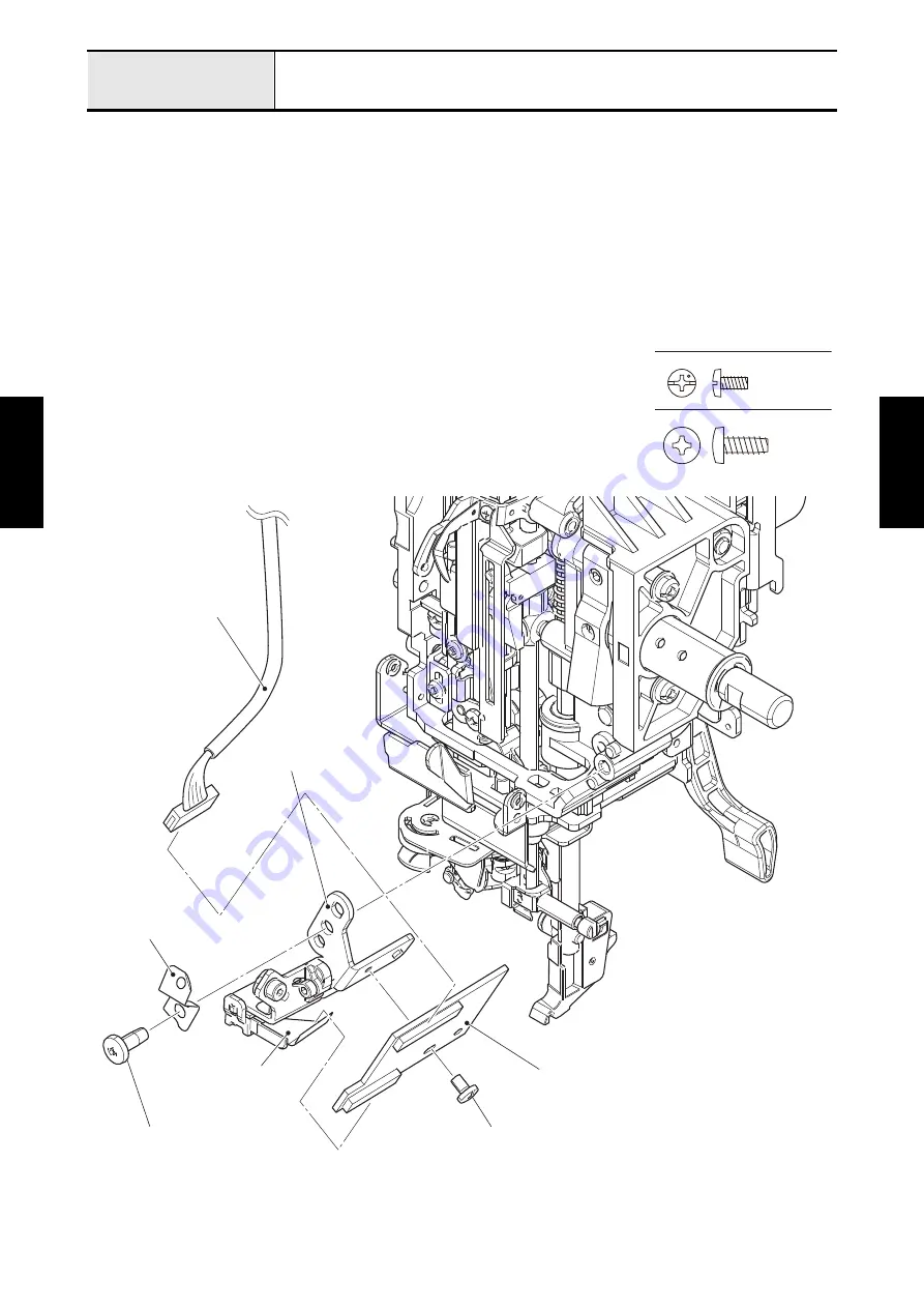
5. Attach the camera relay PCB assy to the CMR holder base with the screw (screw, bind M3x6).
*Key point
• Check that the boss part of the CMR holder base engaged with the positioning hole of the camera relay PCB
assy.
6. Connect the FFC of the camera module to the camera relay PCB assy, and lock it.
7. Connect the lead wire assy camera relay to the camera relay PCB assy, and lock it.
8. Attach the
CMR holder base
and the earth plate with the screw (taptite, bind B M4x10).
*Key point
• Check that the positioning holes of the CMR holder base engaged with the bosses of the needle-presser
module.
Screw, Bind M3X6
Taptite, Bind B M4X10
Earth plate
Lead wire assy camera relay
CMR holder base
Taptite, bind B M4x10
FFC of the
camera module
Camera relay PCB assy
Screw, bind M3x6
Summary of Contents for BLDY
Page 2: ......