


Basic of
D
isassembly
Basic of Disassembly
2 - 20
Electric parts and Main motor unit
Basic of
D
isassembly
5
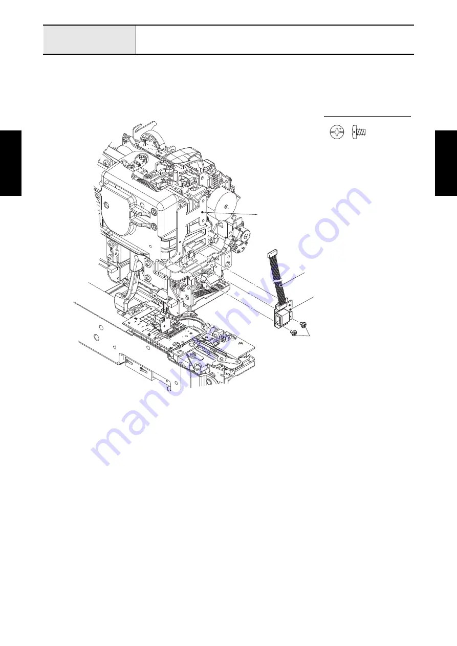
Removal of Extension IF PCB assy
1. Release the extension IF PCB assy lead wire from the securing fixtures.
2. Remove the two screws (screw, bind M3x4) to remove the extension IF PCB assy from the extension
connector holder U.
Screw, Bind M3X4
Extension IF PCB assy
Screw, bind M3x4
Extension connector holder U
Extension IF PCB assy lead wire
Summary of Contents for BLDY
Page 2: ......