


Application of
Assembly
3 - 126
Bobbin winding mechanism
Application o
f
Assembly
Application of
Assembly
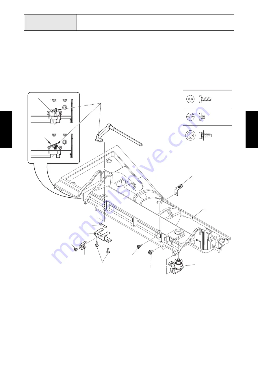
4. Set the thread guide supporting plate to the bobbin winder unit cover, and then tighten the screw
(taptite, bind B M3x8).
5. Align the positioning hole of tension guide assy with the boss of bobbin winder unit cover, and attach
the tension guide assy to the bobbin winder unit cover with the screw (screw, pan (S/P washer) M3x8).
6. Align the positioning hole of notch plate with the boss of sub spool pin holder, and attach the notch
plate to the sub spool pin holder with the screw (screw, bind M3x3).
7. Set the sub spool stand pin to the bobbin winder unit cover, insert the shaft into the sub spool stand pin,
and set the shaft on the mounting position. Attach the sub spool pin holder to the bobbin winder unit
cover with the two screws (taptite, bind B M3x8).
Screw, Pan (S/P washer) M3X8
Taptite, Bind B M3X8
Screw, Bind M3X3
Thread guide supporting plate
Tension guide assy
Screw, pan (S/P washer)
M3x8
Taptite, bind B M3x8
Notch plate
Screw, bind M3x3
Sub spool pin holder
Shaft
Sub spool stand pin
Bobbin winder unit cover
Taptite, bind B M3x8
Taptite, bind B M3x8
Sub spool pin holder
Shaft
Summary of Contents for BLDY
Page 2: ......