


Basic of
D
isassembly
Basic of Disassembly
2 - 8
Main frame and covers
Basic of
D
isassembly
5
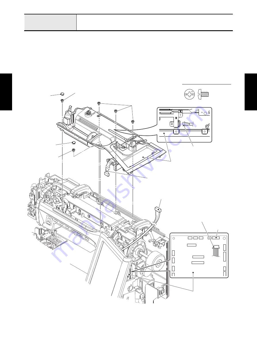
Removal of Bobbin winder unit cover assy
1. Remove the two screw caps from the bobbin winder unit cover assy, and remove the five screws
(screw, bind M4x6) from the bobbin winder unit cover assy.
2. Disconnect the connector of lead wire assy BW from the main PCB assy.
3. Remove the bobbin winder unit cover assy from the machine. Disconnect the lead wire assy RGBLED
from the RGB LED PCB assy of the bobbin winder unit cover assy.
Refer to 3 - 23 "Disassembly of Bobbin winder unit cover assy".
Screw, Bind M4X6
Screw, bind M4x6
Screw cap
Screw, bind M4x6
Connector of lead wire assy BW
Bobbin winder unit cover assy
Screw cap
Screw, bind M4x6
Main PCB assy
CN9
Lead wire assy BW
Connector of lead wire assy RGBLED
Lead wire assy RGBLED
Summary of Contents for BLDY
Page 2: ......