


Basic of
D
isassembly
Basic of Disassembly
2 - 31
LED lamp / Upper driving mechanism
Basic of
D
isassembly
3
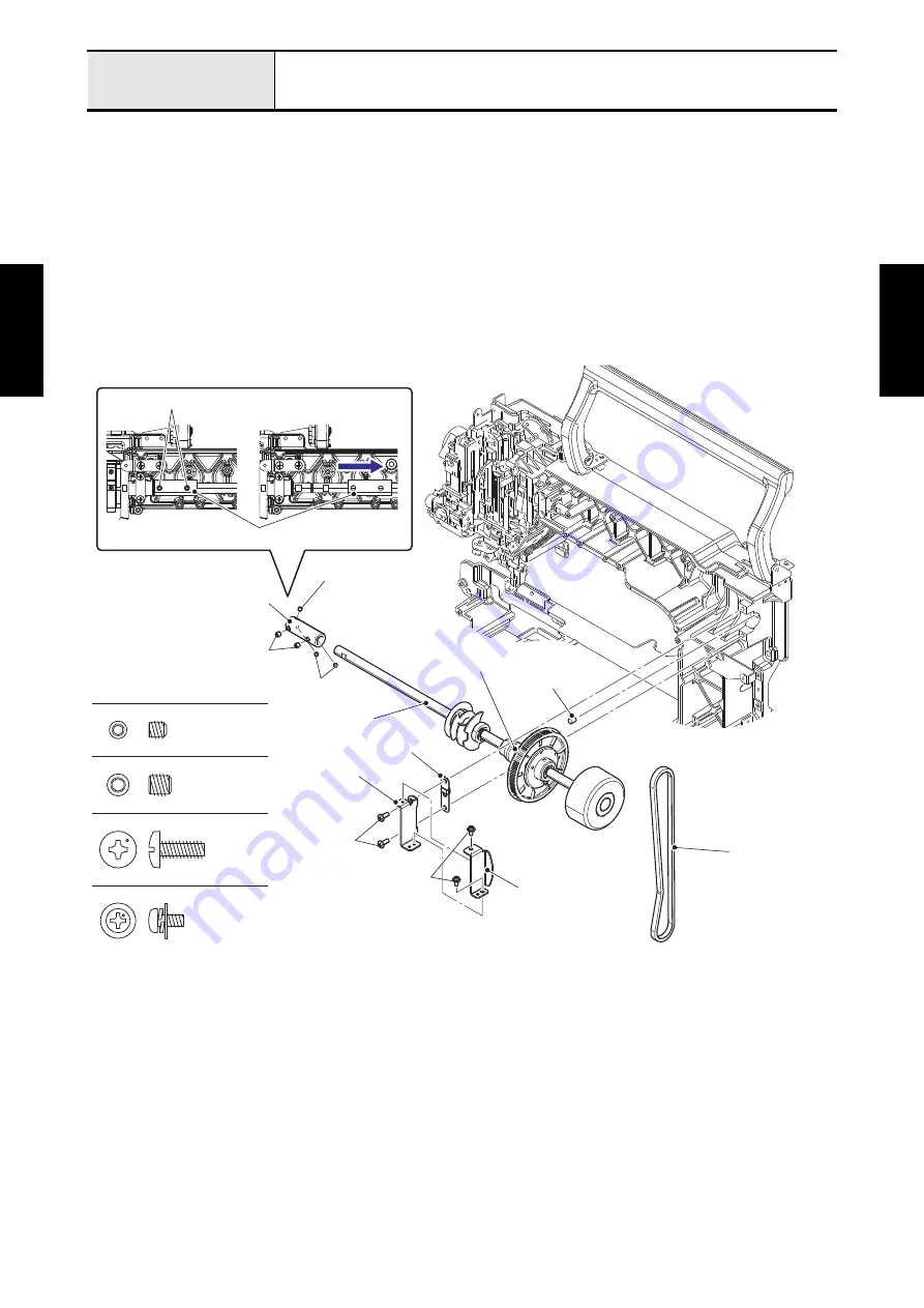
Removal of Upper shaft assy
1. Remove the three screws (set screw, socket (CP) M4x4) and two screws (set screw, socket (FT) M5x5)
from the fixed joint. Slide the fixed joint to the direction of the arrow, and then remove the upper shaft
assy.
Refer to 3 - 43 Disassembly of Upper shaft assy.
2. Remove the two screws (taptite, bind S M4x10) to remove the belt support upper and the metal
presser. Remove the two screws (screw, pan (S/P washer) M3x6) to remove the belt support upper
adjust from the belt support upper.
3. Remove the fixed joint and timing belt from the upper shaft assy.
4. Remove the felt from the arm bed.
Screw, Pan (S/P washer) M3X6
Set Screw, Socket (FT) M5X5
Set Screw, Socket (CP) M4X4
Taptite, Bind S M4X10
Set screw, socket
(CP) M4x4
Felt
Timing belt
Belt support upper adjust
Upper shaft assy
Belt support upper
Taptite, bind
S M4x10
Fixed joint
Set screw, socket (FT) M5x5
Set screw, socket (FT) M5x5
Fixed joint
Metal presser
Screw, pan (S/P washer)
M3x6
Upper shaft metal
Set screw, socket
(CP) M4x4
Summary of Contents for BLDY
Page 2: ......