


Application of
Assembly
3 - 106
LED light / Upper driving mechanism
Application o
f
Assembly
Application of
Assembly
3
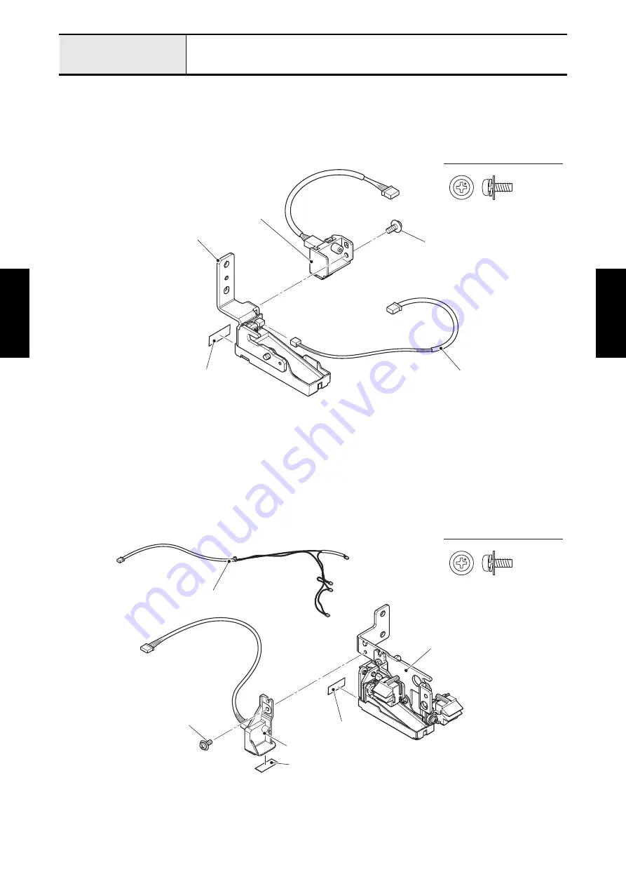
Assembly of LED lamp holder R assy
1. Attach the sheet to the LED lamp holder R assy.
2. Attach the UWR R assy to the LED lamp holder R assy with the screw (screw, pan (S/P washer) M3x8).
3. Connect the lead wire assy LED3 to the LED lamp holder R assy.
4
Assembly of LED lamp holder L assy
1. Attach the sheet to the LED lamp holder L assy.
2. Attach the UWR L assy to the LED lamp holder L assy with the screw (screw, pan (S/P washer) M3x8),
and attach the sheet to the UWR L assy.
3. Connect the four connector of lead wire assy LED2 to the LED lamp holder L assy.
*Key point
• Refer to
"Wiring of Lead wire assy LED2/3"
.
Screw, Pan (S/P washer) M3X8
Lead wire assy LED3
Screw, pan (S/P washer) M3x8
LED lamp holder R assy
UWR R assy
Sheet
Screw, Pan (S/P washer) M3X8
Lead wire assy LED2
Screw, pan (S/P washer) M3x8
UWR L assy
Sheet
LED lamp holder L assy
Sheet
Summary of Contents for BLDY
Page 2: ......