


Application of
Assembly
3 - 156
Needle-presser module
Application o
f
Assembly
Application of
Assembly
5
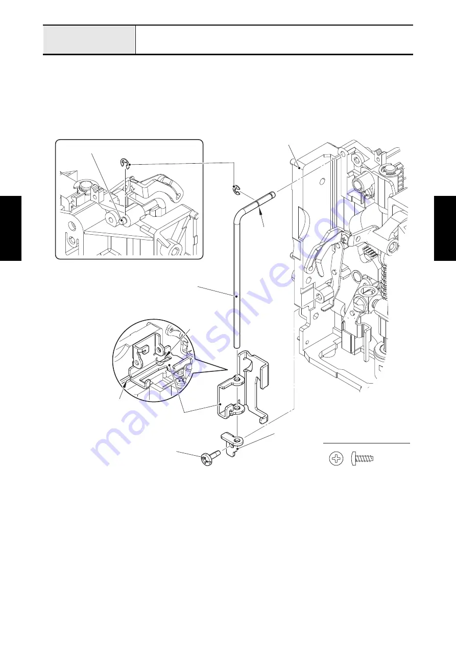
Attachment of Lever AB
1. Attach the retaining ring E2 to the groove A on lever guide shaft. Attach the lever guide shaft to the
upper unit holder assy, and attach the retaining ring E2 to the lever guide shaft.
2. Set the lever AB to the lever guide shaft, and put the sliding part of lever AB on the groove of upper unit
holder assy. Set the lever supporter plate to the lever guide shaft, and attach the lever supporter plate
to the upper unit holder assy with the screw (taptite, bind B M3x8).
Taptite, Bind B M3X8
<Back of upper unit holder assy>
Retaining rings E2
Groove
Slide part
Taptite, bind B M3x8
Lever supporter plate
Lever AB
Lever guide shaft
Groove A
Lever guide shaft
Upper unit holder assy
Summary of Contents for BLDY
Page 2: ......