


Application of
Assembly
3 - 114
Needle threading mechanism
Application o
f
Assembly
Application of
Assembly
2
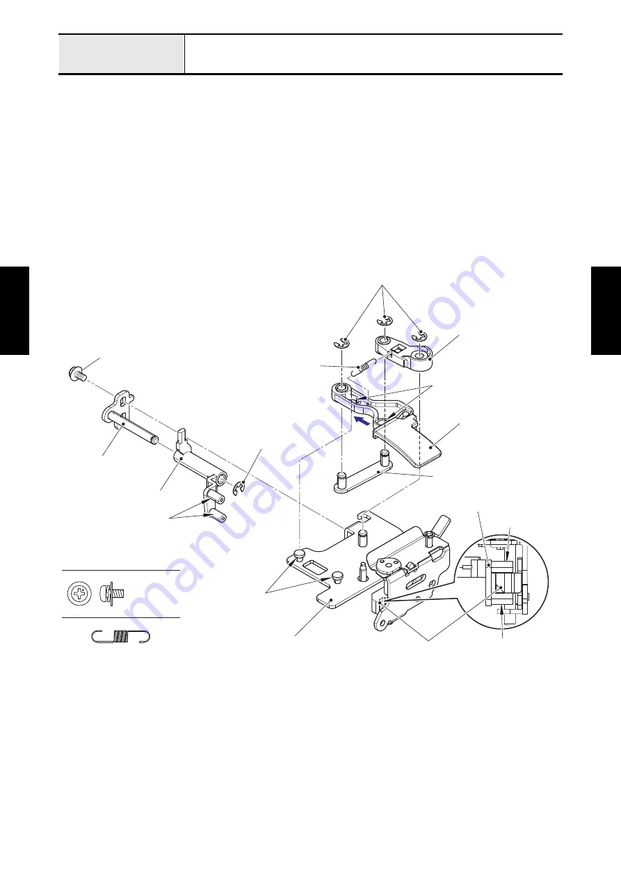
Attachment of Thread guide shutter link A/B/C
1. Insert the link A shaft plate assy into the thread guide shutter link A, and attach the retaining ring E3.
2. Set the tension release cam between the two shafts of thread guide shutter link A. Align the positioning
hole of link A shaft plate assy with the boss of tension release unit, and attach the link A shaft plate
assy to the tension release unit with the screw (screw, pan (S/P washer) M3x6).
3. Set the thread guide shutter link B to the shaft of tension release unit, and attach the retaining ring E3.
4. Align the two positioning holes of thread guide shutter link C with the two bosses of tension release unit,
set the thread guide shutter link C to the tension release unit, and slide it to the direction of the arrow.
5. Insert the two shafts of TH guide shutter link D assy into the thread guide shutter link B and thread
guide shutter link C, then attach the two retaining rings E3.
6. Attach the spring tension (XE4328) to the thread guide shutter link B and the thread guide shutter link
C.
SPRING TENSION (XE4328)
Screw, Pan (S/P washer) M3X6
Retaining rings E3
Positioning holes
Thread guide shutter link C
TH guide shutter link D assy
Thread guide shutter link A
Shaft
Tension release cam
Bosses
Shafts
Retaining ring E3
Thread guide shutter link A
Link A shaft plate assy
Screw, pan (S/P washer) M3x6
Shaft
Thread guide shutter link B
Spring tension (XE4328)
Tension release unit
Summary of Contents for BLDY
Page 2: ......